Cisco UCS E Series Installatiehandleiding - Pagina 37
Blader online of download pdf Installatiehandleiding voor {categorie_naam} Cisco UCS E Series. Cisco UCS E Series 46 pagina's. Ucs e series unified computing system
Ook voor Cisco UCS E Series: Productoverzicht (8 pagina's), Handleiding voor probleemoplossing (28 pagina's)
Removing the PCIe Assembly
Procedure
Connect the wrist strap clip to an unpainted portion of the chassis frame to channel unwanted ESD
Step 1
voltages to ground.
Turn off power to the router.
Step 2
Note
Using either a number 1 Phillips screwdriver or a small flat-blade screwdriver, unscrew the captive
Step 3
screws on the faceplate. Loosen the cover faceplate and remove it (see the following figure). Save the
screws.
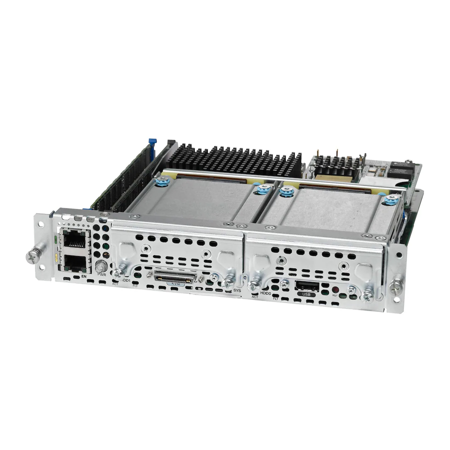
Figure 17
Removing the PCIe Assembly
1
Captive screws on the face plate
3
Plastic bracket screw
Remove the M3 screw holding the flex assembly in place and save the screw for later use.
Step 4
Remove the flex assembly and set it aside.
Step 5
OL-26447-03
Alternatively, the Cisco 3900 ISR G2 and the Cisco ISR 4451-X support OIR. See the
Insertion and Removal" section on page
1
Replacing the PCIe Assembly in a Double-Wide E-Series Server
29.
2
3
4
2
Flex assembly screw
4
PCIe assembly
Hardware Installation Guide for Cisco UCS E-Series Servers
"Online
37