Motorola GM360 Service-informatie - Pagina 11
Blader online of download pdf Service-informatie voor {categorie_naam} Motorola GM360. Motorola GM360 32 pagina's. Gm series professional radio uhf (403-470mhz)
Ook voor Motorola GM360: Service-informatie (34 pagina's), Service-informatie (32 pagina's)

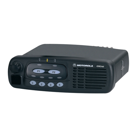
Controlhead Model for GM160, GM360 and GM660
3.3
Microprocessor Circuit
The controlhead uses the Motorola 68HC11E9 microprocessor (µP) (U0831) to control the LED's
and the LCD and to communicate with the host radio. RAM and ROM are contained within the
microprocessor itself.
The microprocessor generates it's clock using the oscillator inside the microprocessor along with a 8
MHz ceramic resonator (U0833) and R0920 .
The microprocessor's RAM is always powered to maintain parameters such as the last operating
mode. This is achieved by maintaining 5V at µP pin 25 . Under normal conditions, when the radio is
off, USW 5V is formed by FLT A+ running to D0822. C0822 allows the battery voltage to be
disconnected for a couple of seconds without losing RAM parameters. Diode D0822 prevents radio
circuitry from discharging this capacitor.
There are 8 analogue to digital converter ports (A/D) on the µP . They are labeled within the device
block as PE0-PE7. These lines sense the voltage level ranging from 0 to 5V of the input line and
convert that level to a number ranging from 0 to 255 which can be read by the software to take
appropriate action.
Pin VRH is the high reference voltage for the A/D ports on the µP . If this voltage is lower than +5V
the A/D readings will be incorrect. Likewise pin VRL is the low reference for the A/D ports. This line is
normally tied to ground. If this line is not connected to ground, the A/D readings will be incorrect.
The microprocessor can determine the used keypad type and the controlhead ID by reading the
levels at ports PC0 – PC7. Connections JU0852/3/4 are provided by the individual keypads.
The MODB / MODA input of the µP must be at a logic „1" for it to start executing correctly. The XIRQ
and the IRQ pins should also be at a logic „1".
Voltage sense device U0832 provides a reset output that goes to 0 volts if the regulated 5 volts goes
below 4.5 volts. This is used to reset the controller to prevent improper operation.
3.4
SBEP Serial Interface
The host radio (master) communicates to the controlhead µP (slave) through its SBEP bus. This bus
uses only line BUS+ for data transfer. The line is bi-directional, meaning that either the radio or the
controlhead µP can drive the line. The microprocessor sends serial data via pin 50 and D0831 and it
reads serial data via pin 47. Whenever the microprocessor detects activity on the BUS+ line, it starts
communication.
When the host radio needs to communicate to the controlhead µP , it sends data via line BUS+. Any
transition on this line generates an interrupt and the µP starts communication. The host radio may
send data like display information, LED and back light status or it may request the controlhead ID or
the keypad ID.
When the controlhead µP wants to communicate to the host radio, the µP brings request line CH
REQUEST to a logic „0" via µP pin 62. This switches on Q0823, which pulls line ON OFF CONTROL
high through diode D0821. A low to high transition on this line informs the radio, that the controlhead
requires service. The host radio then sends a data request message via BUS+ and the controlhead
µP replies with the data it wanted to send. This data can be information like which key has been
pressed or that the volume knob has been rotated.
The controlhead µP monitors all messages sent via BUS+, but ignores any data communication
between host radio and CPS or Universal Tuner.
2-5
