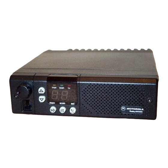
Motorola RADIUS GM300 Servicehandleiding - Pagina 40
Blader online of download pdf Servicehandleiding voor {categorie_naam} Motorola RADIUS GM300. Motorola RADIUS GM300 49 pagina's. 16-channel, conventional fm radio
Ook voor Motorola RADIUS GM300: Servicehandleiding (28 pagina's), Gebruiksaanwijzing (18 pagina's), Gebruiksaanwijzing (19 pagina's), Gebruikershandleiding (37 pagina's), Gebruiksaanwijzing (2 pagina's)

Overview
Push-on jumpers, located on the logic board, allow the operation of the radio to be customized to speciÞc applica-
tions, as explained below. This section contains information about the possible positions for each jumper, and the
corresponding options.
Jumper Positions
The standard position of each jumper, as shipped from the factory, is indicated in bold .
JU551
JU601
JU651
**JU701
**JU808
*JU809
*Present on 2-layer masked logic board (HLN8074) only.
**Present on 4-layer expanded logic board (HLN8070) only
March, 1997
POSITION (A)
The receiver audio applied to the accessories connector J3
(not de-emphasized) and unmuted.
POSITION (B)
The receiver audio applied to the accessories connector J3 pin 11 is de-em-
phasized and muted. Muting is controlled by the RX MUTE output from
the microcomputer, as determined by carrier or tone squelch status.
POSITION (A)
The high-speed receive data path to the microcomputer is Þltered to re-
move audio information below 300 Hz. This is used when decoding sig-
naling data or tones which do not contain low frequency information.
POSITION (B)
The high-speed receive data path to the microcomputer is essentially ßat
over the frequency range of less than 1 Hz to 3 kHz. This is used when de-
coding signaling data which includes very low frequency components.
POSITION (A)
Selects low microphone audio sensitivity, which is 80 mV rms
of full system deviation.
POSITION (B)
Selects high microphone audio sensitivity, which is 40 mV rms for 60% of
full system deviation. This position is not recommended in applications
where high ambient noise is present.
POSITION (A)
J3-5 functions as a Flat TX Audio Input which is routed through the limit-
er. Response is 0.6-3000 Hz. Sensitivity is 180 mV rms for 60% of full sys-
tem deviation.
POSITION (B)
J3-5 functions as an External PL Input, bypassing the limiter. Response is
0.7-300 Hz.
POSITION (A)
Pin 12 of accessories connector J3 functions as a programmable I/O (in-
put or output) as determined by the RSS.
POSITION (B)
Pin 12 of accessories connector J3 functions as the SCI+ programming line.
It is connected directly to the SCI+ line on microphone connector J11.
POSITION (A)
Allows the use of a remote desk set which is connected to accessories con-
nector J3. Pin 14 functions as the HOOK line. When pulled low, the radio
is forced into the monitor (off-hook) position. Note that this is the opposite
polarity of the HOOK function on the microphone connector J11.
POSITION (B)
Allows the use of an HLN3145 Public Address system. Pin 14 of accesso-
ries connector J3 functions as the PA ENABLE line. In the public address
mode this line is pulled low, inhibiting transmit PTT operation, but leav-
ing all other radio functions unchanged.
Note: When a R*I*C*K Repeater adapter is used, the push-on jumper
JU809 must be removed entirely.
Jumper-Selectable Options
68 No.
Section 3
pin 11 is flat
for 60%
3-1
