Motorola GP340 ATEX Service-informatie - Pagina 3

Blader online of download pdf Service-informatie voor {categorie_naam} Motorola GP340 ATEX. Motorola GP340 ATEX 30 pagina's. Professional radio, power distribution and controller
Ook voor Motorola GP340 ATEX: Specificatieblad (5 pagina's), Gebruikershandleiding (31 pagina's), Specificatieblad (2 pagina's), Gebruikershandleiding (30 pagina's), Gebruikershandleiding (30 pagina's), Basis gebruikershandleiding (10 pagina's), Service-informatie (32 pagina's), Service-informatie (30 pagina's), Service-informatie (26 pagina's), Service-informatie (24 pagina's), Service-informatie (31 pagina's), Service-informatie (43 pagina's)
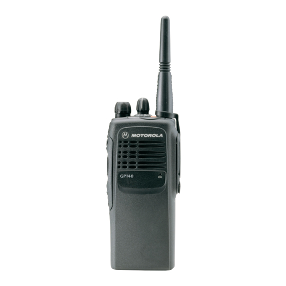
Motorola GP340 ATEX Service-informatie

Table of Contents

Chapter 1
THEORY OF OPERATION
1.0 Overview ..............................................................................................................1-1
2.0 Radio Power Distribution .....................................................................................1-1
3.0 Controller Circuits ................................................................................................1-2
3.1 Controller Architecture....................................................................................1-2
3.2 MCU Digital Architecture ................................................................................1-2
3.3 Real Time Clock .............................................................................................1-3
3.4 ModB/Vstby Supply ........................................................................................1-4
3.5 Audio/Signaling Architecture ..........................................................................1-4
Chapter 2
TROUBLESHOOTING CHARTS
1.0 UHF/ UHF2 Controller..........................................................................................2-1
1.1 All models except those with PCB 8486458Z03.............................................2-1
1.2 Models with PCB 8486458Z03 .......................................................................2-2
Chapter 3
CONTROLLER SCHEMATICS
1.0 Allocation of Schematics and Circuit Boards .......................................................3-1
2.0 Controller - Set 1 (PCB 8480450Z03, 8485641Z02, 8480587Z01,
3.0 Controller - Set 2 (PCB 8480450Z13/14, 8485641Z06).......................................3-9
4.0 Controller - Set 3 (PCB 8486458Z03, 8486686Z02)..........................................3-15
8485677Z01, 8480641Z03) ......................................................3-3
iii