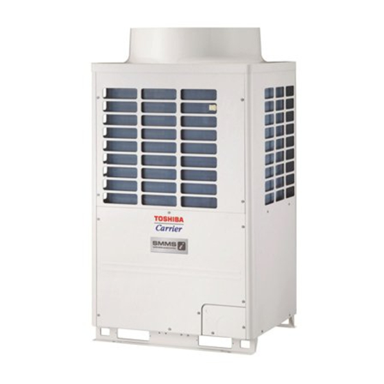
Toshiba Carrier MMY-MAP1446FT9P-UL Installatiehandleiding - Pagina 19
Blader online of download pdf Installatiehandleiding voor {categorie_naam} Toshiba Carrier MMY-MAP1446FT9P-UL. Toshiba Carrier MMY-MAP1446FT9P-UL 33 pagina's.

1. All system interconnecting and central control wiring should be 2 conductor shielded cable.
2. On the header unit the control wire shield and the central control wire shield should both be connected to the
same ground screw in the header unit.
3. The remote control wiring can be 2 conductor un-shielded cable.
4. All system interconnecting and control wiring should be sized per table 5, 6 and 7.
5. Control wire and power line wire between Flow selector unit and indoor unit are the accessory parts of single
port Flow selector unit. (Wire length : 20 ft (6 m))
If the length between indoor unit and Flow selector unit exceeds 16 ft (5 m), connect by using the Connection
cable kit sold separately (RBC-CBK15UL). (Except Multi port FS unit)
Restriction of control wiring
Be sure to keep the rule of below tables about size and length of control wiring.
Central
control
device
Super modular multi system
U1
U2
U3
U4
Header
Header
Follower
unit
unit
unit
U3 U4
U3 U4
U3 U4
Outdoor
unit
U1 U2
U5 U6
U1 U2
U5 U6
U1 U2
U5 U6
L1
L2
Indoor
U1 U2
U1 U2
U1 U2
unit
A
B
A
B
A
B
Remote
Remote
control
control
Table-5
Control wiring between indoor and outdoor units (L1, L2, L3), Central control wiring (L4)
Wiring
2-core
Type
Shielded cable
Size/Length
AWG16: Up to 3280 ft (1000 m) AWG14: Up to 6560 ft (2000 m) (*1)
(*1): Total length of control wiring length for all refrigerant circuits (L1 + L2 + L3 + L4)
Table-6
Control wiring between outdoor units (L5)
Wiring
2-core
Type
Shielded wire
Size/Length
AWG16 to AWG14 / Up to 330 ft (100 m) (L5)
Table-7
Remote control wiring (L6, L7), Multi port FS unit wiring (L8)
Wiring
2-core, non-polarity
Type
AWG20 to AWG14
• Up to 1640 ft (500 m) (L6 + L7)
• Up 1310 ft (400 m) in case of wireless remote control in group control.
• Up to 660 ft (200 m) total length of control wiring between indoor units and Multi port FS unit
Size/Length
(L6+L8)
• Up to 980 ft (300 m) (L6 + L7 + L8)
• Up to 980 ft (300 m) (L7)
35-EN
Table-1
L4
Follower
Header
Follower
unit
unit
unit
U3 U4
U3 U4
U3 U4
U1 U2
U5 U6
U1 U2
U5 U6
U1 U2
U5 U6
L5
Table-2
Table-1
L3
U1 U2
U1 U2
U1 U2
U1 U2
U1 U2
A
B
A
B
A
B
A
B
Table-3
L6
L7
Table-3
Remote
control
■ Connection of power supply wires and control wires
Power supply
terminal block
Ground screw
Control wire
terminal block
Control wires
Wire clamp
(MAP072, MAP096, MAP120)
NOTE
Separate power supply wires and control wires.
◆ Power supply wire connection
1. Connect the power supply conduit to the field wiring panel.
2. Route the power supply wiring through the raceway and connect to the power supply terminal block and ground
A
B
Table-3
screw.
L8
3. Use ring terminals on field power wires if required by NEC and local codes.
A B
A B
A B
A B
Multi port FS unit
Knockout for control wires
NOTE
Bundle the control wires in the cutout so that they do not get caught in the electrical control box cover.
– 18 –
Power supply wires
Wire clamp
Power supply
terminal block
Ground screw
Control wire
terminal block
Wire clamp
Control wires
Conduit
(MAP144, MAP168)
A Knockout for power supply wires
(When using wire size AWG 14, AWG 12, or AWG 10.)
B Knockout for power supply wires
(When using wire size AWG 8, AWG 6, or AWG 4.)
Piping/wiring panel
Power supply wires
Wire clamp
Conduit
EN
FR
36-EN
