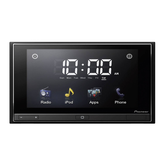
Pioneer AppRadio SPH-DA01 Installatiehandleiding - Pagina 5
Blader online of download pdf Installatiehandleiding voor {categorie_naam} Pioneer AppRadio SPH-DA01. Pioneer AppRadio SPH-DA01 40 pagina's. Display unit appradio
Ook voor Pioneer AppRadio SPH-DA01: Bedieningshandleiding (32 pagina's), Bedieningshandleiding (36 pagina's), Belangrijke informatie voor de gebruiker (24 pagina's), Firmware-updates (4 pagina's)

Connecting the system
To prevent damage
WARNING
! Use speakers over 50 W (output value)
and between 4 W to 8 W (impedance value).
Do not use 1 W to 3 W speakers for this
unit.
! The black lead is ground. Please ground
this lead separately from the ground of
high-current products such as power
amps. Do not ground more than one pro-
duct together with the ground from an-
other product. For example, you must
separately ground any amp unit away
from the ground of this product. Connect-
ing grounds together can cause a fire and/
or damage the products if their grounds
became detached.
! When replacing the fuse, be sure to only
use a fuse of the rating prescribed on this
product.
! When disconnecting a connector, pull the
connector itself. Do not pull the lead, as
you may pull it out of the connector.
! This product cannot be installed in a vehi-
cle without ACC (accessory) position on
the ignition switch.
ACC position
! To avoid short-circuiting, cover the discon-
nected lead with insulating tape. It is espe-
cially important to insulate all unused
speaker leads, which if left uncovered may
cause a short circuit.
! Refer to the owner's manual for details on
connecting the power amp and other units,
then make connections accordingly.
! Since a unique BPTL circuit is employed,
do not directly ground the * side of the
speaker lead or connect the * side of an-
No ACC position
other side of the speaker lead together. Be
sure to connect the * side of the speaker
lead to the * side of the speaker lead on
this product.
! If the RCA pin jack on this product will not
be used, do not remove the caps attached
to the end of the connector.
Notice for the blue/white lead
! When the ignition switch is turned on (ACC
ON), a control signal is output through the
blue/white lead. Connect to an external
power amp's system remote control term-
inal (max. 300 mA 12 V DC). The control sig-
nal is output through the blue/white lead,
even if the AV source is switched off.
! Be sure not to use this lead as the power
supply lead for the external power amps.
Such connection could cause excessive
current drain and malfunction.
! Be sure not to use this lead as the power
supply lead for the auto-antenna or anten-
na booster. Such connection could cause
excessive current drain and malfunction.
Section
02
5
En
