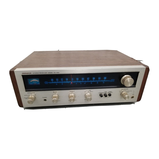
Pioneer SX-424 FVZV Servicehandleiding - Pagina 11
Blader online of download pdf Servicehandleiding voor {categorie_naam} Pioneer SX-424 FVZV. Pioneer SX-424 FVZV 27 pagina's. Am/fm stereo receiver
Ook voor Pioneer SX-424 FVZV: Servicehandleiding (37 pagina's), Gebruiksaanwijzing (12 pagina's)

.
AM
SECTION
a)
Turn
the selector
switch
to
AM.
b)
Connect
the AM
signal generator
to
the
AM
antenna
terminal.
c)
Set
the AM
signal generator
to
modulation
AOOHz,30%,
output
level
30dB, frequency
600kHz.
Set
the
receiver
dial at 600kHz.
d)
Connect
the VTVM and
oscilloscope
(in
parallel)
to
the TAPE
REC
jack.
e)
Observing
the output
level
on the VTVM,
adjust the following
cores
for
maximum
reading.
T8
..
Oscillatorcircuit
Ferrite loopstic
antenna: Antenna circuit
f)
Set the AM
signal generator
and the
re-
ceiver
dial
to
1,400kH2
g)
Observing
the output
level
on the VTVM,
adjust the following
cores
for
maximum
reading.
cT5
.
cT4
.
h)
Repeat alignments
(e)
to
(g)
several times.
i)
After
these alignments,
lock the
trimmer
capacitor
with
paint.
7.3
MPX DECODER ALIGNMENT
a)
Modulate
the FM
signal generator
output
by
FM MPX modulator.
b)
Turn
the selector
switch
to FM
AUTO.
c)
Connect the FM
signal generator
to
the FM
antenna terminals.
d)
Set
the FM MPX modulator
to modulation;
main
lkHz
(L+R)
6OVo,
pilot
8
-
LOVo.
e)
Set the output level
of
the FM
signal
generator
to
60dB.
f)
Turn the
tuning knob
to
maximum
reading
on the
signal meter.
g) Set the
modulation
of the FM
MPX
modulator
to
pilot
only.
sx-424
h)
Connect
the
oscilloscope
to
TP2.
i)
Adjust the
transformere
(T13, T14,
T15)
until
the output
level
of
the 19kHz
be-
comes
maximum on the
scope.
j)
Set the FM MPX modulator
to pilot
with L
or
R
signal.
k)
Connect
the
dual-trace
oscilloscope
and
VTVM to
the TAPE
REC jacks.
l)
Adjust
the semi-fixed potentiorneter on
the
tuner
unit
until
the
output
level
of
the
L or
R
signal
becomes
maximum
on
the
scope.
7.4
OTHER ALIGNMENT
o
CHECKING THE SCA
FILTER
a)
Connect the FM
signal generator
to
the FM
antenna terminals.
b)
Modulate
the FM
signal generator
con-
nected
to
the
audio
generator, check
that
the
frequency
response
shows troughs at
around
67
kHz
and.
7
ZkHz.
o
CHECKING THE STEREO INDICATOR
a)
Connect the FM
signal generator
to
the FM
antenna terminals.
b)
Turn the
selector
switch
to
FM AUTO.
c)
Modulate
the FM
signal generator
con-
nected
to
the FM
MPX modulator,
and
set
the FM MPX
modulator
pilot
on.
Ctreck
that the
stereo
indicator lamp
goes
in.
Then set
the
FM
MPX
modulator
to pilot
off,
and
check
that the
stereo
indicator
lamp
goes
out.
ogr.,oo
oootf'o-
;
Tq
oH@
@'6
c
6l
8o.4-'L'"!'ro-;
;
ce,
6@ @
@
0
ra
VT,u
Trz
a>
l=
6ab
-Tre
'rrz
O@
,
@ @
6a\ofd\
o
Don o o o oP o 9o
r
o o
o
o
TUNER
UNIT
(AWE-OO8)
11
