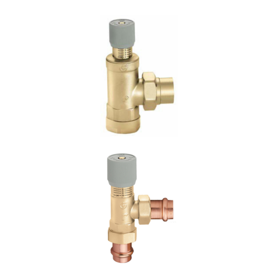
CALEFFI 519709A Snelstarthandleiding - Pagina 2
Blader online of download pdf Snelstarthandleiding voor {categorie_naam} CALEFFI 519709A. CALEFFI 519709A 4 pagina's. Adjustable differential pressure by-pass valve with graduated scale
WARNING: This product can expose you to chemicals including lead, which is
known to the State of California to cause cancer and birth defects or other
reproductive harm. For more information go to www.P65Warnings.ca.gov.
CAUTION: All work must be performed by
proper application, installation, and maintenance of systems in accordance
with all applicable codes and ordinances.
CAUTION: Over-tightening and breakage can occur with the use of T
pipe joint compounds. T
exercised not to over-tighten joints. Failure to follow these instructions
could result in property damage and /or personal injury.
WARNING: System
hazardous. Be sure the pressure has been reduced to zero and the
system temperature is below 100°F (38°C). Failure to follow these
instructions could result in property damage and/or personal injury.
Operating principle
2
5
1
3
4
System operation
O = open
C = close
Two-way
O
C
O
O
O
O
O
C
O
C
O
O
1
1
2
2
3
3
4
5
5
4
mH
2
O
6
mH
2
O
6
provides lubricity so that care must be
®
s are under pressure or temperature can be
When the spring (1) compression is adjusted using the control
knob (2), the force balance acting on the valve plug (3) changes,
thus modifying the threshold pressure value of the valve. The valve
plug opens, activating the by-pass circuit, only when it is subjected
to a di
rential pressure su
the thrust exerted by the spring. This allows the
through the outlet (4), limiting the di
the two points in the system where the valve is
The job of the di erential pressure by-pass valve is to maintain the
pump operating point as close as possible to its nominal value (point
A on the graph shown below). If the by-pass valve is not used, when
the ow rate in the circuit decreases due to partial closure of the two-
way zone valves, the head loss in the circuit increases, point B.
The by-pass valve, set to the nominal head value of the pump,
limits the increase in pressure, by-passing the
behavior is guaranteed at any closing condition of the system two-
way zone valves. In fact, once the position of the valve control
knob has been established, the threshold pressure value is more
or less constant as the discharge
characteristic diagrams).
A proper valve sizing must guarantee a su cient
keep the pump at its nominal operating point in all system operating
conditions, for example when the rst zone valves are closed.
∆p
∆p
Circuit resistance curve
NOMINAL
with two-way valves
partially open
d personnel trained in the
t to generate a thrust greater than
rence in pressure between
w rate ∆G. This
w rate varies (see hydraulic
w rate by-pass to
B
A
∆p constant
on the cir cuit
Circuit resistance curve with
two-way valves fully open
∆G
50%
100%
®
w discharge
Pump curve
Flow rate G