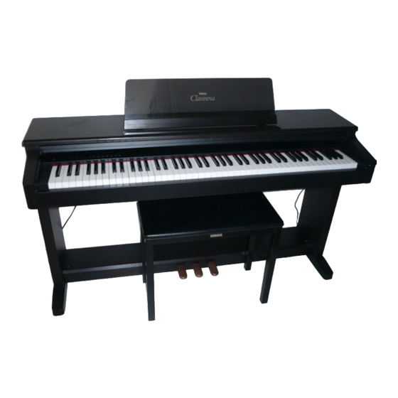
Yamaha Clavinova CLP-124 Gebruikershandleiding - Pagina 24
Blader online of download pdf Gebruikershandleiding voor {categorie_naam} Yamaha Clavinova CLP-124. Yamaha Clavinova CLP-124 36 pagina's. Yamaha clavinova owner's manual

4
The illustrations here are not available.
V
Attach the side panels (E) to the pedal
box (C).
Attach the side panels (E) to the corresponding ends of
the pedal box (C), making sure that the power cord on one
side and the pedal cord on the other fit into the grooves in
the side panels (E). Each side panel is attached to the pedal
box using four medium gold screws 2 inserted from in-
side the pedal box.
B
Install the cable covers (G).
Stand the pedal box/side panel assembly upright and fit
the power and pedal cords into the corresponding side
panel grooves with the connectors protruding from the
recesses at the top of each groove, as shown in the illustra-
tion. Slide a cable cover (G) down into the recessed part of
each groove with the notched end of the cover upwards.
Slide the cable covers down until they stop against the
pedal box, then make sure that the upper part of the covers
are properly fitted in the grooves. Make sure that the ribs
extending from the cable covers go inside the guides in
each groove, as shown in the illustration.
N
Install the metal brace (D).
Place the long metal brace on top of the upper brackets
at the front (pedal side) of the side panels, with the flanged
edges of the brace facing upward. Attach the brace with
one small black screw 3 at each end.
84
V
Befestigen Sie die Seitenwände (E) am
Pedalkasten (C).
Bringen Sie die Seitenwände (E) so an den beiden
Enden des Pedalkastens (C) an, daß das Netzkabel an der
einen und das Pedalkabel an der anderen Seite in den
Nuten der Seitenwände (E) zu liegen kommt. Beide
Seitenwände werden mit jeweils vier mittellangen
goldenen Schrauben 2 festgemacht, die vom Inneren des
Pedalkastens her einzuschrauben sind.
B
Bringen Sie die Kabelabdeckungen (G)
an.
Stellen Sie die halbfertige Pedalkasten/Seitenwand-
Baugruppe auf, und legen Sie dann das Netz- und das
Pedalkabel in die zugehörige Nut der Seitenwand, so daß
die Stecker wie in der Abbildung am oberen Ende
herausragen. Schieben Sie jeweils eine Kabelabdeckung
(G), mit dem gekerbten Ende nach oben weisend, von oben
her in die beiden Nuten. Schieben Sie die
Kabelabdeckungen bis zum Anschlag gegen den
Pedalkasten, und prüfen Sie dann, ob die oberen Enden der
beiden Abdeckungen sicher in der jeweilingen Nut sitzen.
Die beiden Längsrippen der Abdeckung müssen fest in der
Führung sitzen, wie in der Abbildung gezeigt.
N
Schrauben Sie die Metallstrebe (D) fest.
Legen Sie die Metallstrebe (D) mit der flachen Seite
nach unten auf die beiden Winkelbleche an der vorderen
Seite (Pedalseite) der Seitenwände. Schrauben Sie die
Strebe mit jeweils einer kleinen schwarzen Schraube 3 an
beiden Enden fest.
