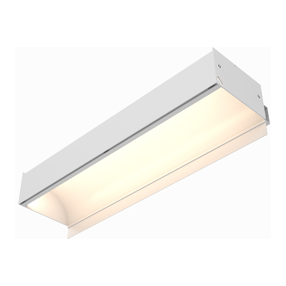
CALI alumLEDs ALS500T-RMW-HC Handleiding voor installatie-instructies - Pagina 8
Blader online of download pdf Handleiding voor installatie-instructies voor {categorie_naam} CALI alumLEDs ALS500T-RMW-HC. CALI alumLEDs ALS500T-RMW-HC 16 pagina's.
Ook voor CALI alumLEDs ALS500T-RMW-HC: Handleiding voor installatie-instructies (16 pagina's)

8
Adjust Cable Gripper by unscrewing locking mechanism. Press down and hold
the threads where cable feeds through. Pull cable from the exit. Let go of threads
to lock in place, then replace locking mechanism.
Unscrew & lift
9
Slide luminaires onto Aircraft Cable Assemblies. Remove Connector Blocks if
applicable. Replace after Aircraft Cable Assemblies are installed.
Always install corner luminaires first.
10
If applicable, install end cap to end of run.
CALIFORNIA ACCENT LIGHTING, INC.
2820 E. Gretta Lane, Anaheim, CA 92806
ph. 800.921.CALI (2254) | fx. 714.535.7902 | [email protected] | calilighting.com
© CALI. All rights reserved. CALI reserves the right to make changes or withdraw specifications without prior notice.
Press down & hold
Pull cable
Slide luminaires onto
Aircraft Cable Assemblies
ALS500T-RMW-HC
Mounting (Aircraft Cable Assembly) 2 of 3
11
All aircraft cables must rest in a vertical position. Do not allow aircraft cables to
rest at a slant or angle. Adjust as needed.
Note: The position of the Aircraft Cable Assemblies may deviate from the
spacing diagrams on page 11 due to variations within the installation area.
Ensure all luminaires are appropriately balanced.
12
Secure connections between continuous runs using Connector Blocks after all
luminaires have been mounted.
Note: Refer to steps on page 12 for details.
13
Install Ceiling Trim after all luminaires have been mounted and connected.
Note: Follow the steps on page 13 to install Ceiling Trim.
14
After all luminaires are mounted, adjust height and levelness of each luminaire
by adjusting cable gripper. Use a dummy piece of drywall to perfect the height at
which the luminaires will rest. The drywall will be tucked into the gap between
the Hard Ceiling Trim and the concealed ceiling grid when hung.
Note: One person holds the luminaire and another person adjusts cable gripper.
Trim excess cable
15
If applicable, position the driver in the center of luminaire and secure using set
screws (by others). Do not mount drivers between luminaires.
Note: Driver size and location of mounting holes may differ from below example.
INSTALLATION INSTRUCTIONS
Adjust length as needed
Hard Ceiling Trim flush with
projected location of ceiling drywall
Ceiling Line
5 / 20 / 2021 / Rev 3
Page 8 of 16
