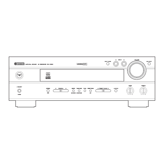
Yamaha DSP-AX530 Servicehandleiding - Pagina 21
Blader online of download pdf Servicehandleiding voor {categorie_naam} Yamaha DSP-AX530. Yamaha DSP-AX530 21 pagina's. Av receiver/av amplifier

7. RX-V430/HTR-5540/DSP-AX430: Removal of MAIN
(10) and MAIN (2) P.C.B.s
a. Remove 4 screws (D). (Fig. 3)
b. Remove MAIN (10) P.C.B.. (Fig. 6)
c. Remove 1 screw (E). (Fig. 3)
d. Remove 1 screw (F). (Fig. 6)
e. Remove MAIN (2) P.C.B.. (Fig. 6)
MAIN (4) P.C.B.
C
B
FUNCTION (5) P.C.B
RX-V530/RX-V530RDS/HTR-5550/HTR-5550RDS/DSP-
AX530/RX-V430RDS/HTR-5540RDS
Replacement of Power Transistor, Speaker
Protective Relay
It is easy to replace the power transistor and speaker
protective relay of this unit according to the following
procedure.
a. Remove the top cover. (Refer to "1. Top Cover
Removal" on p.18.)
b. Remove 1 screw (B) and 2 screws (C). (Fig. 6)
c. Raise the MAIN P.C.B. (Fig. 7)
d. In this state, the power transistor and speaker
protective relay can be replaced. To check the
operation in this state, it is necessary to connect the
grounding cable.
RX-V530/RX-V530RDS/HTR-5550/HTR-5550RDS/DSP-AX530
RX-V430/RX-V430RDS/HTR-5540/HTR-5540RDS/DSP-AX430
F
MAIN (2) P.C.B.
MAIN (7) P.C.B.
CB253
C
MAIN (3) P.C.B.
MAIN (1) P.C.B.
Fig. 6
Fig. 7
7. RX-V430/HTR-5540/DSP-AX430: MAIN (10) 、
MAIN (2) P.C.B.の外し方
a. Dのネジ4本を外します。 (Fig. 3)
b. MAIN (10) P.C.B.を取り外します。 (Fig. 6)
c. Eのネジ1本を外します。 (Fig. 3)
d. Fのネジ1本を外します。 (Fig. 6)
e. MAIN (2) P.C.B.を取り外します。 (Fig. 6)
MAIN (4) P.C.B.
C
B
FUNCTION (5) P.C.B
RX-V430/HTR-5540/DSP-AX430
パワートランジスタ、スピーカー保護リレーの交換
手順
本機は、パワートランジスタおよびスピーカー保護リレー
を容易に交換することができます。
a. トップカバーを外します。 (18ページ "1. トップカ
バーの外し方" 参照)
b. Bのネジ1本、Cのネジ2本を外します。 (Fig. 6)
c. MAIN P.C.B.を起こします。 (Fig. 7)
d. この状態でパワートランジスタ、スピーカー保護リレー
を交換することができます。
なお、この状態で動作チェックをする場合、アースを接
続する必要があります。
F
MAIN (2) P.C.B.
MAIN (10) P.C.B.
CB253
C
MAIN (3) P.C.B.
MAIN (1) P.C.B.
21
