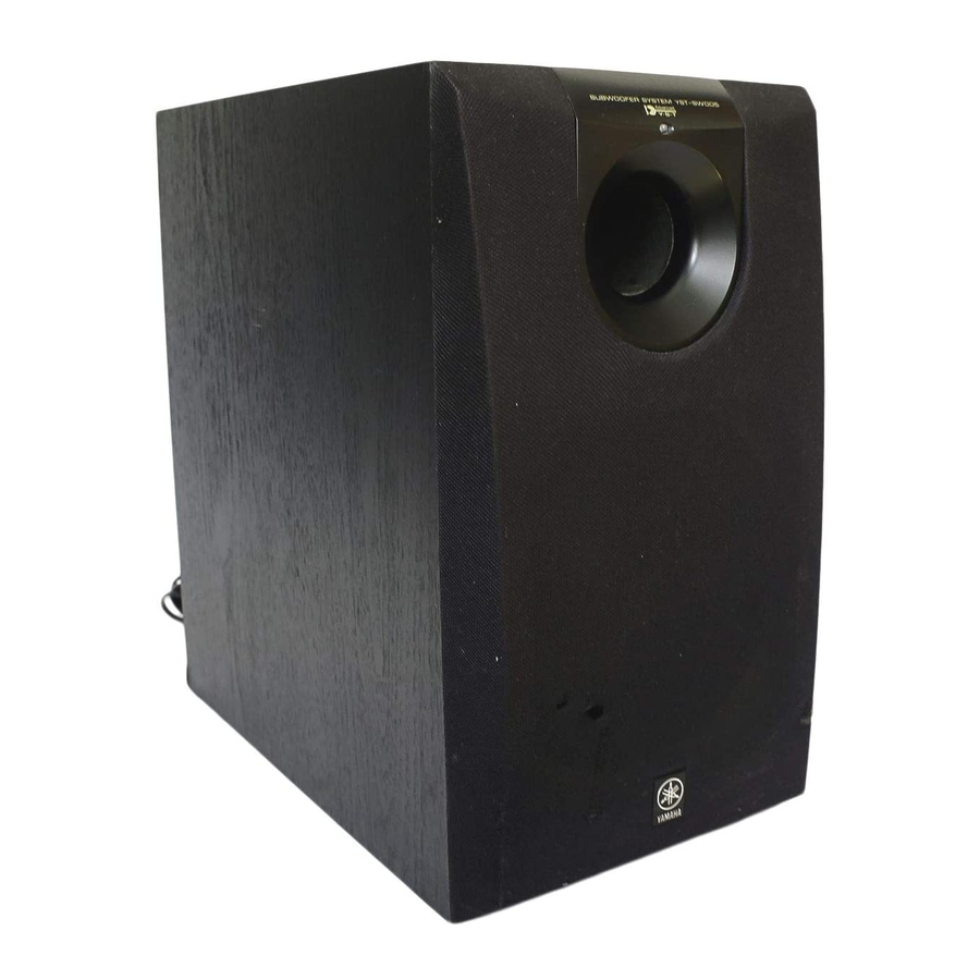
Yamaha YST-SW005 Gebruikershandleiding - Pagina 12
Blader online of download pdf Gebruikershandleiding voor {categorie_naam} Yamaha YST-SW005. Yamaha YST-SW005 19 pagina's. Yamaha subwoofer system owner's manual
Ook voor Yamaha YST-SW005: Gebruikershandleiding (20 pagina's), Servicehandleiding (16 pagina's), Servicehandleiding (13 pagina's)

CONTROLS AND THEIR FUNCTIONS
1
POWER
ON
2
OFF
3
110V-120V
VOLTAGE
SELECTOR
220V-240V
1
Power indicator
Lights up GREEN when the POWER switch (
pressed in to the ON position and goes off when set to
the OFF position.
* Standby mode
If the POWER switch (
position and the AUTO STANDBY switch (
to the HIGH or LOW position, this indicator lights up
RED when no signal is received by the subwoofer.
2
POWER switch
Press this switch to the ON position to turn on the
power of the subwoofer. When the power of the
subwoofer is on, the power indicator (
panel lights up GREEN. Press this switch again to set
to the OFF position to turn off the power of the
subwoofer.
3
VOLTAGE SELECTOR switch
(China and General model only)
If the preset setting of the switch is incorrect, set the
switch to the proper voltage range (220V-240V or
110V-120V) of your area.
Consult your dealer if you are unsure of the correct
setting.
WARNING
Be sure to unplug the subwoofer before setting the
VOLTAGE SELECTOR switch correctly.
8
E-
Front panel
SUBWOOFER SYSTEM YST-SW005
SUBWOOFER SYSTEM YST SW005
Rear panel
VOLUME
0
10
AUTO
HIGH
STANDBY
HIGH CUT
LOW
HIGH
LOW
OFF
INPUT2
/MONO
INPUT1
FROM AMPLIFIER
OUTPUT
TO SPEAKERS
POWER
ON
OFF
220V-240V
VOLTAGE
SELECTOR
110V-120V
2
) is
2
) is pressed in to the ON
4
) is set
1
) on the front
Port
AUTO
STANDBY
4
HIGH
LOW
OFF
5
INPUT2
6
INPUT1
FROM AMPLIFIER
7
OUTPUT
TO SPEAKERS
4
AUTO STANDBY (HIGH/LOW/OFF) switch
This switch is originally set to the OFF position. By
setting this switch to the HIGH or LOW position, the
subwoofer's automatic power-switching function
operates as explained on page 9. If you do not need
this function, set to the OFF position.
* Make sure to change the setting of this switch only
when the POWER switch (
5
INPUT2 terminals
Used to input line level signals from the amplifier.
6
INPUT1 (FROM AMPLIFIER) terminals
Used to connect the subwoofer with the speaker
terminals of the amplifier.
7
OUTPUT (TO SPEAKERS) terminals
Can be used for connecting to the main speakers.
Signals from the INPUT1 terminals (
these terminals.
8
VOLUME control
Adjusts the volume level. Turn the control clockwise to
increase the volume, and counterclockwise to
decrease the volume.
9
HIGH CUT (HIGH/LOW) switch
Selects the high frequency cut off point.
Normally, it is set to LOW, however, you may set to
HIGH if necessary. Refer to page 10.
VOLUME
8
0
10
9
HIGH
HIGH CUT
LOW
/MONO
2
) is in the OFF position.
6
) are sent to
