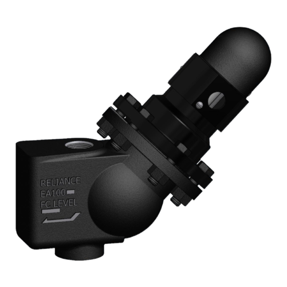
Clark-Reliance Levalarm EA100SP Instructies voor installatie en gebruik - Pagina 10
Blader online of download pdf Instructies voor installatie en gebruik voor {categorie_naam} Clark-Reliance Levalarm EA100SP. Clark-Reliance Levalarm EA100SP 10 pagina's.

2. Test the unit for proper functioning
a. To test the switch assembly, set the head assembly in a vise and make sure that
b. Attach an ohm meter to the common and normally open switch contact and
c. Then, move the ohm meter terminal from the normally open terminal to the
3. If the unit fails to test properly, contact Clark-Reliance for further instructions to adjust
the switch mechanism or to obtain authorization to return the unit for factory inspection.
If the switch tests OK, return unit to service.
4. Reassemble the unit. Reinstall the Switch head assembly onto the body with a new C1-
3 gasket and apply a Teflon based sealant to both sides of the gasket. Lubricate the
bolts with a Nickel based high temperature lubricant and torque the 4 or 6 bolts to 70
FT-LB, in 1/3 increments.
PART NUMBER
EA100-14X
SWITCH ASSEMBLY
F3S
FLOAT
C1-3
GASKET
X172372
CAP BOLT
X171501
NUT
T***RK
'T' probe for models with probes (up to 250 PSI)
V***RK
'V' probe for models with probes (251 to 800 PSI)
*** =
Probe Length measured from gasket surface of Probe fitting body. First (2) digits indicate length in whole inches, 3rd digit indicates
additional one-eighths of an inch.
Warning: If this equipment is used in a manner not specified by Clark-Reliance, the protection
provided by the equipment may be impaired. Only replacement parts manufactured by Clark-Reliance
should be used to ensure safety and reliable operation.
The use of non-Clark-Reliance parts will void the factory warranty and any agency approvals.
Order genuine Clark-Reliance replacement parts at:
local Clark-Reliance Representative.
Any additional questions should be directed to your local Clark-Reliance Representative, or to the
Factory: Phone: (440) 572-1500 Fax: (440) 238-8828
the switch housing is on the same 45 degree angle as if it were mounted on the
boiler piping.
manually move the float up and down and verify the switch operates on both
directions. The meter should indicate continuity only when the switch is operated
in the closed position.
normally closed terminal and repeat the test. The meter should indicate an open
circuit only when the switch is in the open position.
DESCRIPTION
SPARE PARTS
http://parts.clark-reliance.com
or contact your
