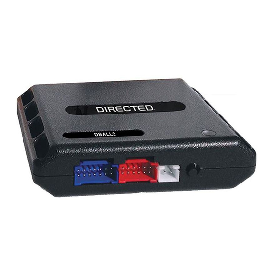
Directed XpressKit DBALL Handmatig - Pagina 7
Blader online of download pdf Handmatig voor {categorie_naam} Directed XpressKit DBALL. Directed XpressKit DBALL 19 pagina's. Ford5 remote start ready (rsr) installation
Ook voor Directed XpressKit DBALL: Installatiehandleiding (16 pagina's), Handmatig (14 pagina's), Installatiehandleiding (16 pagina's)

Platform: DBALL/DBALL2
Firmware: FORD5 Remote Start Ready (RSR) Installation
Installation Diagram Type 3
Important!
The Hood Pin and Remote Start Safety Override Switch are mandatory safety devices, but are NOT supplied with the DBALL.
Refer to the Vehicle Wiring Reference Chart for more information on specific wiring and connections.
(+) Parking Lights Left: Yellow/Blue, pin 1
(+) Parking Light Right: Brown/Yellow, pin 26
6 Amp
diodes
86
87
(+) 12V
87a
Fuse 15A
Junction Connector C238
(behind glove compartment)
21
9
33
22
10
1
23
11
34
2
24
12
35
3
25
13
36
4
HS CAN Low:
26
14
White, pin 15
27
15
5
37
28
16
HS CAN High:
6
38
29
17
White/Blue,
39
7
30
18
pin 16
31
19
40
8
32
20
(-) Brake Interrupt :
Violet/White, pin 3
Violet/Gray,
pin 34
(+) PTS:
Not required in D2D mode.
With the exception of the OBDII Diagnostic connector, all adapters are displayed from the wire side (unless specified otherwise).
C2280A (BCM)
22
23
24
25
26
27
28
29
30
85
32
33
34
30
35
36
37
MS CAN Low:
38
Violet/Orange,
39
pin 40
40
MS CAN High:
42
Gray/Orange,
pin 41
MS CAN High: Tan/Black: 3
MS CAN Low: Tan: 4
HS CAN High: Orange/Green: 5
HS CAN Low: Orange/Brown: 6
(+) 12V
(+) Brake Input: Brown: 7
(+) Brake Output: Yellow: 8
Brake Interrupt (veh. side): Orange/Red: 10
Brake Interrupt (conn. side): Yellow/Red: 11
(+) 12V
(-) Ground
(-) Parking Light: Red/Black: 4
(+) Push-To-Start Output: Gray/Black: 7
Data TX: Yellow/Black: 10
Data RX: Orange/Black: 11
C2280C (BCM)
20
40
60
19
39
59
18
38
58
17
37
57
16
36
56
15
35
55
14
34
54
RX:
13
33
53
TX:
12
32
52
Yellow/Orange,
11
31
51
pin 54
10
30
50
9
29
49
8
28
48
7
27
47
pin 28
6
26
46
5
25
45
44
4
24
3
23
43
2
22
42
1
21
41
1
2
3
4
5
6
7
8
9
31
10
11
12
13
14
(+) Brake:
15
pin 16
16
17
18
19
41
20
21
(+)12V: Red: 13
Ground: Black: 14
RF
Prog. Button
LED
Rev.: 20160317
BCM (passenger side, behind glove box)
The Remote Start
Safety Override Switch
MUST be in the OFF
position.
Hood Pin
Remote Start Safety
Override Switch
6: White/Black: (-) Hood
DBALL/
DBALL2
You can connect to either a XL202
RFTD OR a SmartStart module.
Refer to the SmartStart/XL202
Installation Notes for more information.
© 2016 Directed. All rights reserved.
Page 7
