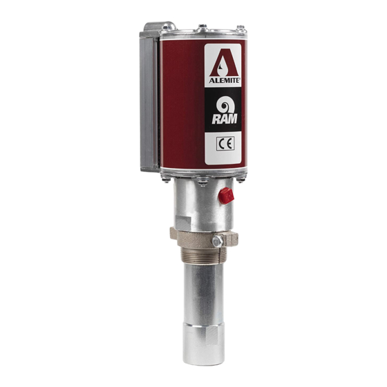
Alemite 9968-A Servicehandleiding - Pagina 9
Blader online of download pdf Servicehandleiding voor {categorie_naam} Alemite 9968-A. Alemite 9968-A 16 pagina's. Low-pressure stub pump
Ook voor Alemite 9968-A: Servicehandleiding (11 pagina's)

Overhaul
NOTE
Refer to fig. 3, page 12 and
IPB 1, page 14 for component
identification on all overhaul procedures
Prior to performing any maintenance
procedure, the following safety precautions
must be observed Personal injury may
occur
WARNING
Do not use halogenated hydrocarbon
solvents such as methylene chloride or
1,1,1-trichloroethane in this pump
An explosion can result when aluminum
and/or zinc-plated parts in pump come
in contact with halogenated hydrocar-
bon solvents
Release all pressure within system
prior to performing any overhaul
procedure
• Disconnect air supply line from pump
motor
• Into an appropriate container, oper-
ate control valve to discharge
remaining pressure within system
Never point a control valve at any
portion of your body or another person
Accidental discharge of pressure and/or
fluid can result in injury
Read each step of instructions care-
fully Make sure a proper understanding
is achieved before proceeding
Disassembly
Separate air motor from
pump tube
1 Clamp pump assembly in a soft-jaw vise at
bung adapter (22) or body (8)
2 Remove cover (1a)
2.1 Pry and swing cover sideways away
from cylinder (→ SER 670782 for
details)
3 Remove screw (1b) from top cap
4 Remove nuts (1d) that secure body to air
motor assembly (1)
5 Remove carriage bolts (1c) from top cap
5.1 Remove keepers (9) from body
6 Remove the cap from the cylinder
CAUTION
Remove cylinder with care
Damage to quad-ring (6) and/or
o-ring (7) can occur
7 With a side-to-side motion, pull cylinder
from body and air piston (4)
8 Remove o-ring (7) from body
9 Remove bottom cap from body
Pump tube assembly
Tube assembly
1
Unscrew tube (21) from body
Step for model 9968 and 9968-m only:
2
Remove bung adapter from tube as
required
3
Remove o-ring (19) and back-up
ring (20) from tube
Air piston assembly
4 Remove screw (2) that secures air
piston (4) to rod (15)
4.1 Remove air piston from rod
5
Remove washer (3) quad-ring (6), and
o-ring (5) from air piston
9
Rod assembly
6 Pull rod assembly from bottom of body
7 Unscrew valve seat (18) from rod
7.1 Remove ball (17) and nylon piston (16)
Body assembly
8 Remove o-ring (7) from body
9 Remove washer (14), spacer (13) and seal
(12) from body
10 Remove bearing (11) and seal (10) from
body
Step for model 9968-M only:
11 Unscrew adapter (29) from body only when
necessary
11.1 Adapter is secured with threadlocker
Foot valve assembly
12 Unscrew foot valve (27) from tube (21)
13 Remove o-ring (26) from foot valve
14 Remove pin (28) from foot valve
15 Remove washer (23), spring (24), and ball
(25) from foot valve
Clean and inspect
NOTE
Use appropriate repair kit for replace-
ment parts Make sure all components
are included in kit before discarding
used parts
1 Clean all metal parts in cleaning solvent
Solvent should be environmentally safe
2 Inspect all parts for wear and/or damage
2.1 Replace as necessary
3 Inspect air piston (4) for fatigue cracks
3.1 Replace as necessary
4 Inspect nylon piston (16) and rod (15) closely
Use a magnifying glass to detect any
score marks on the rod
4.1 Replace as necessary
5 Closely inspect mating surfaces of all check
valve components for any imperfections
Ensure a smooth and clean contact is
obtained when assembled
Example: place ball (25) into
foot valve (27) Fill foot valve with solvent
Make sure no leakage occurs
