Directed Electronics Xpresskit DBALL Installatiehandleiding - Pagina 3
Blader online of download pdf Installatiehandleiding voor {categorie_naam} Directed Electronics Xpresskit DBALL. Directed Electronics Xpresskit DBALL 14 pagina's. Databus all combo bypass module
Ook voor Directed Electronics Xpresskit DBALL: Installatiehandleiding (14 pagina's)

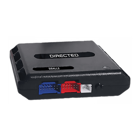
Platform: DBALL/DBALL2
Firmware: GM5 Remote Start Ready (RSR) Installation
Wiring Diagram
Important!
The Hood Pin and Remote Start Safety Override Switch are mandatory safety devices, but are NOT supplied with the DBALL.
Green or Black
Connector located
at the ignition switch.
BCM Side
6 5
4 3
2
1
Key
Side
(+) 12V
(+) 12V
(+) 12V
(-) Ground
R. Code In (Car Side): Violet/Green: 8
R. Code Out (Car Side): Violet/Brown: 9
(-) Parking Lights Output: Blue/Red: 12
Driver Door Trigger:
Gray/Black, pin A32
B8
B5
B4
B1
A48
A6
A43
A1
(-)Parking Lights: Brown/White, pin 2
BCM
Black Connector
56-pin
With the exception of the OBDII Diagnostic connector, all adapters are displayed from the wire side (unless specified otherwise).
The position of the R. Code wire may vary.
Test this wire using the following chart:
- 12V at Key Input
- 4.3V at Ignition
- 0V at Accessory
- 5V at Start
J1850: Violet/Yellow: 2
(+) 12V Input: Brown: 7
Accessory Output: Yellow: 8
(+) Ignition Output: Yellow/Red: 11
(+) 12V Input: Brown/Red: 12
(+) 12V: Red: 13
(-) Ground: Black: 14
(-) RAP Off : Black/White: 1
RF
Prog. Button
LED
1
6
14
7
Headlight Switch
Connector
J1850: Violet, pin 2
1
8
9
16
Diagnostic connector
OBDII (connector side view)
DBALL/
DBALL2
Driver Front Pillar
2011-12 (Canyon/H3)
3
1
Brake Switch 2004-06
Hood Pin
The Remote
Start Safety
Override Switch
MUST be in the
Remote Start Safety
OFF position.
Override Switch
6: White/Black: (-) Hood Input
7: Pink/White: (+) Brake Input
You can connect to either a XL202
RFTD OR a SmartStart module.
Refer to the SmartStart/XL202
Installation Notes for more information.
© 2015 Directed. All rights reserved.
Rev.: 20150626
Page 3
4
OR
2
