Clarus Technologies WCS-25 Gebruikershandleiding - Pagina 8
Blader online of download pdf Gebruikershandleiding voor {categorie_naam} Clarus Technologies WCS-25. Clarus Technologies WCS-25 16 pagina's. Cleaning stations
Ook voor Clarus Technologies WCS-25: Gebruikershandleiding (14 pagina's)

bend the fusible link. Tighten all bolts. Once the light/lid bar assembly is secured,
connect the male plug of the light bar to the female plug labeled "light bar" out of the
electrical box.
C.
Establish Work Area
1. Create a properly sized area where the Cleaner will be located. This area should
be a level, solid working area with sufficient overhead room for the light/lid bar
assembly. A 110 volt 15 amp circuit should be within 6 feet of this area.
2. Place the Cleaner in working area with a forklift or pallet jack with front of unit
facing out.
3. Use front leveling feet to reduce any rocking from an uneven floor. The leveling
feet should not be used to raise the unit off the floor. Use a Bubble level to level
Front/Back and Left/Right.
D.
Fill Unit with Solvent
1. Once the unit is set into place, leveled and power plugged in, you can fill it with
solvent. The 15 Series requires 17.5 gallons of solvent. The 25 Series requires
27.5 gallons of solvent.
2. NOTE: If your unit is equipped with a fluid level gauge, fill with solvent until
fluid level gauge (located on front left corner) reads full. If there is no fluid level
gauge, the fill line is located underneath the filter access cover on the tank wall.
Do not fill the solvent past the FILL LINE indicated by the decal.
3. Make sure both the cleaning brush and fluid nozzle are inside the tank before
turning the system on. Turn system on with the switch labeled "Solvent Flow"
(NOTE: Models built prior to June 2012 were equipped with a 4-minute timer
and a green push button.)
4. Turn the unit off and check fluid level and fill to solvent line if needed.
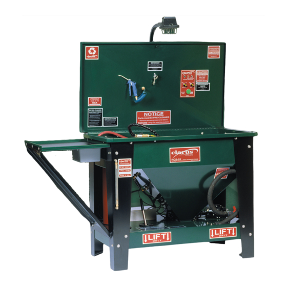
Optional Equipment Installation – Pre-Clean Shelf
E.
1. Confirm all pieces and necessary parts
a. (3) sets of: Bolts with washers, lock washers & nuts.
b. (1) Green pre-clean shelf with cut out
c. (1) Black support bracket/brace
d. (1) Black plastic shelf liner/insert
e. (1) Grey plastic bin
NOTE: Do not tighten all the bolts until each one has been installed and hand
tightened.
2. From the left side of the unit:
a. Remove inner leg attachment bolts from both Top & Bottom.
b. Install green pre-clean shelf into top holes.
8
