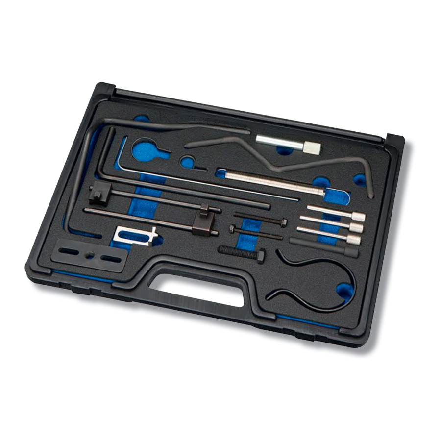
CLAS OM 4102 Handmatig - Pagina 9
Blader online of download pdf Handmatig voor {categorie_naam} CLAS OM 4102. CLAS OM 4102 12 pagina's. Timing tools psa/fiat 1.4-1.6-2.0-2.2 diesel

OM 4102
TIMING TOOLS PSA/FIAT 1.4-1.6-2.0-2.2 DIESEL
5. Insert the VS4735/P17 Camshaft Locking Pin through the camshaft
2
sprocket and into the datum point in the cylinder head g.1.
6. Ensure that the crankshaft key is in the11-0-clock position and insert
the VS4735/P15 Locking Pin to con rm correct crankshaft position
g.2.
7. One of the VS4735/P15 Locking Pins is used to lock the crankshaft,
and the other one locks the HP fuel pump.
8. Check the HP pump alignment using the holes in the pump sprocket.
Note: If there is no corresponding hole in the pump bracket to the
hole in the sprocket, align by positioning the holes in the sprocket
vertically.
9. S upport the engine and remove the RH engine mounting,
release the timing belt tensioner and remove the old timing belt.
Reassembly:
3
10. Ensure the camshaft sprocket, crankshaft and the HP fuel pump
are aligned correctly and locked in their locked in their timing positions
as previously described.
11. Fit the new timing belt and re- t the engine mounting.
12. Apply tension to the belt by turning the tensioner anticlockwise
until the pointer is positioned between the sides of the window g.3.
13. Re- t crankshaft position sensor and belt guide angle bracket.
Note: Do not touch the magnetic track (sensor ring).
14. Remove all tooling and carefully rotate the crankshaft through 10
revolutions in the direction of rotation.
15. Re-check the engine timing as previously described, ensuring that the camshaft, crankshaft and HP fuel pump
sprocket are correctly aligned.
16. Remove all tooling and check the belt tensioner pointer is correctly positioned.
17. Insert Locking Pin VS4735/P16 into the ywheel and re- t the crankshaft pulley ensuring a new securing bolt
is used.
2.0HDi and 2.2HDi engines
This range of engines requires the use of the VS1210/01 Crankshaft Pulley Remover to extract the crankshaft pulley
to allow the timing belt to be removed. Due to its location, the ywheel timing datum hole can be dif cult to access,
there are 3 Flywheel Locking Pins included in this kit, to cover all ywheel types including dual mass ywheels.
Solid ywheel datum holes are located behind the starter motor, dual mass ywheel datum holes are located on
the cylinder block inboard of the right hand drive shaft.
Two tools are included in the kit for the adjustable crankshaft gear position which was introduced on some variants
in 2001.
There are also two types of belt tensioner adjusters; this kit contains the tools for both types.
1. Remove the lower bell housing cover, t the VS1286 Flywheel Holding Tool g.4.
2. Release the crankshaft pulley securing bolt. Once the pulley bolt is released, remove the VS1286 Flywheel
Holding Tool.
Note: VS1286 is also used when re tting the crankshaft pulley bolt. Locking Pins must NOT be used to hold the
crankshaft when releasing or tightening the
