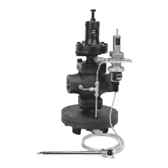
Armstrong OB 2000PT Instructies voor installatie, bediening en onderhoud - Pagina 6
Blader online of download pdf Instructies voor installatie, bediening en onderhoud voor {categorie_naam} Armstrong OB 2000PT. Armstrong OB 2000PT 6 pagina's. Pressure/temperature regulating valve

Problem
Temperature Regulator
does not reach desired
set temperature.
Temperature rises
excessively.
Large variation
between thermometer
and temperature
regulator setting.
External leak.
Armstrong-Yoshitake, Inc.
Bulletin No. AY-731-A
1/03
Troubleshooting Guide
Cause
Improper adjustment.
Faulty steam trap draining equipment.
Inadequate pressure to eliminate
condensate.
Bellows follower (10) was not installed.
No transfer medium applied to sensor.
Incorrect capillary range.
Improper adjustment.
Dirt or scale on main valve (6) and main
valve seat (7) or flawed valve and seat.
Dirt or scale on pilot valve and stem (3),
pilot valve seat (4).
Fitting orifice (30B) is blocked.
Broken capillary system.
By-pass line leaks.
Thermal bulb or thermometer are installed in
wrong location. See Page 1.
Inlet pressure too high.
Dirt or scale on pilot valve and stem (3),
guide (7) and pilot valve seat (4), main
spindle (9) is dirty.
Body gasket leaks.
Broken top bellows seal (5).
, 221 Armstrong Blvd., P.O. Box 408, Three Rivers, MI 49093 - USA Ph: (269) 279-3600 Fax: (269) 273-8656
www.armstrong-intl.com
Solution
Re-adjust according to Regulating Methods
on Pages 2 and 3.
Check trap and correct problem.
Re-pipe system.
Install bellows follower.
Apply heat transfer paste to thermal bulb
before installing in well.
Check label and change to correct range.
Re-adjust according to Regulating Methods
on Pages 2 and 3.
Disassemble and clean valve and seat, see
Page 3 for disassembly. In case of flawed
valve and seat replace them.
Disassemble pilot and clean.
See Page 3 for disassembly.
Remove and clean.
Replace capillary system.
Repair by-pass line.
Relocate the thermal bulb so the fluid freely
flows around 3/4" of the bulb and/or relocate
the thermometer closer to the thermal bulb.
Lower inlet pressure. On low load
applications, the lower the inlet pressure,
the more stable the control will be.
Disassemble and clean.
Tighten bolts and replace gaskets
Replace top bellows seal. Kit K-2611
Printed in U.S.A.
