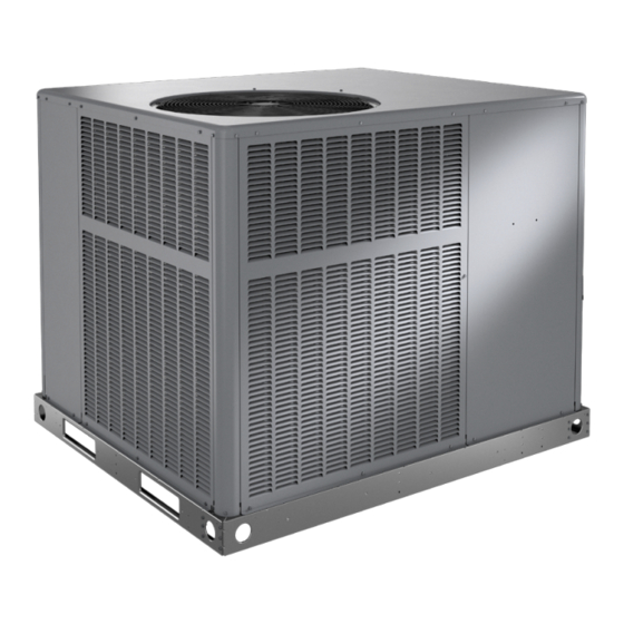
Armstrong Air NP14H Series Handleiding voor installatie- en onderhoudsinstructies - Pagina 11
Blader online of download pdf Handleiding voor installatie- en onderhoudsinstructies voor {categorie_naam} Armstrong Air NP14H Series. Armstrong Air NP14H Series 20 pagina's. Residential packaged units

Before lifting a unit, make sure that the weight is
distributed equally on the cables so that it will lift evenly.
Figure 2.
Unpacking
Locate the four stacking brackets at each corner of the top
panel. Remove the screws and washers that secure these
brackets. All screws must be re-installed. The washers and
stacking brackets can be discarded. Remove the bag and
remaining packaging material, which can be discarded.
Locate the four plastic fork slot bumpers on the base rails.
Remove the fasteners and bumpers and discard.
As with any mechanical equipment, personal injury can
result from contact with sharp sheet metal edges. Be
careful when you handle this equipment.
Service Access
Access to all serviceable components is provided by four
removable panels: upper access panel (for blower, ID coil,
and optional filter), auxiliary heat access, control access
panel, and compressor access.
This unit is charged with HFC-410A refrigerant.
Operating pressures for units charged with HFC-410A
are higher than pressures in units charged with HCFC-
22. All service equipment MUST be rated for use with
HFC-410A refrigerant.
507296G03 / 31-5000670
CAUTION
High Voltage
Power Entry
Thermostat
Wire Entry
Gas Entry
CAUTION
WARNING
All field wiring must be done in accordance with National
Electrical Code recommendations, local codes, and
applicable requirements of UL Standards, or in accordance
with Canadian Electrical Code recommendations, local
codes, or CSA Standards. Power wiring, disconnect
means, and over-current protection are to be supplied by
the installer. Refer to the unit rating plate for maximum
over-current protection and minimum circuit ampacity, as
well as operating voltage. The power supply must be sized
and protected according to specifications supplied.
The unit must be grounded with a separate ground
conductor. See Figure 4 for typical field wiring connection.
The wiring diagram can be found on the unit inside the
access panel. Low voltage control wiring are terminal strip
or pigtail leads located on the main control box and are
color-coded to match the connection called out on the
wiring schematic.
NOTE: An optional bottom-entry power kit is available for
these units. See the kit instructions for proper installation
details.
When connecting electrical power and control wiring
to the unit, waterproof-type connectors must be used
so that water or moisture cannot be drawn into the unit
during normal operation.
Units are factory wired for a 230-volt power supply.
If power supply is 208 volts, it will be necessary to
change a wire connection on the unit transformer from
240V terminal to 208V terminal as shown on the wiring
diagram.
Use only copper conductors.
If any of the original unit wiring is replaced, the same size
and type wire must be used.
Contactor
If 208 Volt is supplied, transformer connection must be
changed
Figure 3. 208/230 Line Voltage Wiring
Issue 2211
Electrical Wiring
CAUTION
Field-Supplied Fused
Ground
or Circuit Breaker
Lug
Disconnect
Page 11 of 20
