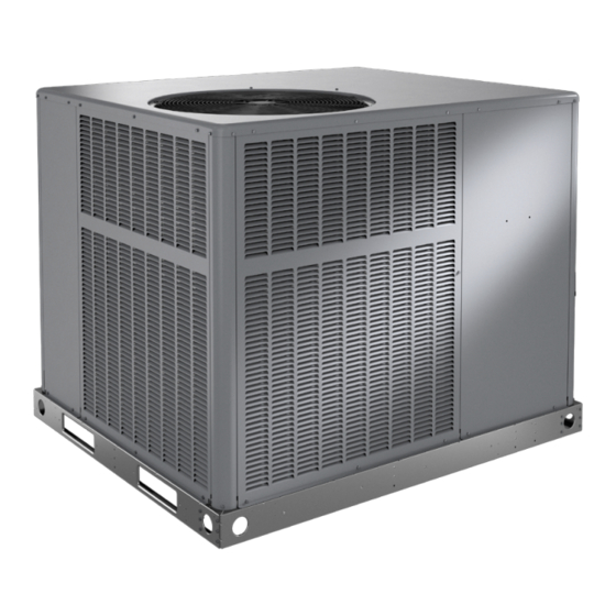
Armstrong Air NP14H Series Handleiding voor installatie- en onderhoudsinstructies - Pagina 14
Blader online of download pdf Handleiding voor installatie- en onderhoudsinstructies voor {categorie_naam} Armstrong Air NP14H Series. Armstrong Air NP14H Series 20 pagina's. Residential packaged units

heater sequencers as well as the indoor blower. Upon
satisfying auxiliary heat demand, the thermostat opens
above circuits and heating elements sequence off; blower
continues to operate until all heating elements have turned
off.
Defrost System
The defrost system includes two components: the defrost
thermostat and the defrost control.
Defrost Thermostat
The defrost thermostat is located on the evaporator coil.
When the defrost thermostat senses 35°F or cooler, the
thermostat contacts close and send a signal to the defrost
control board to start the defrost timing. It also terminates
defrost when the liquid line warms up to 60°F.
Defrost Control
The defrost control board includes the combined functions
of time/temperature defrost control, defrost relay, diagnostic
LEDs and terminal strip for field wiring connections (see
Figure 6).
The control provides automatic switching from normal
heating operation to defrost mode and back. During the
compressor cycle (call for defrost), the control accumulates
compressor run time at 30, 60, 90 minute field-adjustable
intervals. If the defrost thermostat is closed when the
selected compressor run time interval ends, the defrost
relay is energized and the defrost begins.
Page 14 of 20
Figure 7. Heater Kit Accessory Installation
Issue 2211
DEFROST TIMING
PINS (P1)
TEST
PINS
COMPRESSOR
DELAY PINS
REVERSING
VALVE
S87
LOW PRESSURE
SWITCH
DEFROST
THERMOSTAT (S6)
S4
HIGH PRESSURE
SWITCH
Figure 6. Defrost Control Board
1. An on-board outdoor ambient temperature sensor on
the defrost control bypasses the low pressure switch
during low ambient temperature below 15°F in heating
mode to eliminate nuisance low pressure trips.
NOTE: 15°F
is
depending upon model and installation location.
2.
A defrost cycle will initiate when there has been a low
pressure switch trip; the defrost sensor must be closed
and the defrost time interval must not have expired.
DIAGNOSTIC
LEDS
24V TERMINAL
STRIP
CONNECTIONS
SERVICE LIGHT
CONNECTIONS
an
approximate
temperature,
507296G03 / 31-5000670
