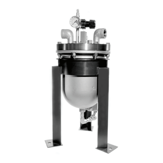
Blacoh SPILLSTOP Installatie- en bedieningshandleiding - Pagina 4
Blader online of download pdf Installatie- en bedieningshandleiding voor {categorie_naam} Blacoh SPILLSTOP. Blacoh SPILLSTOP 12 pagina's. Leak containment system
Ook voor Blacoh SPILLSTOP: Installatie- en bedieningshandleiding (8 pagina's)

Installation & Operation Instructions
Shutoff Valves
Depending on the model, SPILLSTOP includes one to four Shutoff Valves. Additional Shutoff Valves are available from Blacoh.
Pump Shutdown: Installed at the pump inlet, the Pump Shutoff Valve automatically shuts down the pump in the event of a diaphragm
failure. A single SPILLSTOP can protect multiple smaller air operated diaphragm pumps (1/2" or 1" models) by routing all of the pump
exhausts through the SPILLSTOP and installing additional Pump Shutoff Valves for each pump. It is possible to do this with larger
pumps but, there could be a significant reduction in flow due to the restriction added to the pump exhaust.
High Inlet Pressure/Positive Flooded Suction: For applications with positive flooded suction (positive inlet pressure to the pump), it
is recommended to install an additional Shutoff Valve on the pump exhaust line to stop fluid in the tank from flowing through the failed
diaphragm and out of the pump exhaust when the pump is shut down. For purposes of these instructions, this valve is referred to as an
Exhaust Shutoff Valve.
Installation
1. Install the Pump Shutoff Valve directly to the air inlet of the pump (Figure A). This valve can be installed before or after any
regulator or lubricator installed in the compressed air line. Refer to Figures B-D for appropriate valve locations and air line
connections when installing multiple valves.
The Pump Shutoff Valve must be installed so that air flows into the valve through Port A (or Port 1 depending on
valve design), and exits the valve through Port B (or Port 2) towards the pump�
2. Install an exhaust hose with a pressure rating at least as high as the system air pressure, from the pump's air discharge port
(exhaust) to the SPILLSTOP Inlet connection port. Alternatively, rigid piping may be used; however, a minimum 6" (15.2 cm) length
of hose should be used for the connection from the pipe to the Inlet connection port.
3. If using an Exhaust Shutoff Valve when there is positive inlet pressure to the pump, install the Exhaust Shutoff Valve in the pump
exhaust line at the SPILLSTOP Inlet connection port (Figures B and D). This valve will close whenever the pump is shut down,
regardless of whether the SPILLSTOP is activated or not.
4. Connect 1/4" plastic tubing from the Pump Shutoff Valve to Port 2 of the SPILLSTOP Actuator Valve (Figure 1).
Since the Pump Shutoff Valve is a normally closed valve, the pump will not operate unless compressed air is supplied
to the Pump Shutoff Valve. Air supplied to the Pump Shutoff Valve must flow through the SPILLSTOP Actuator Valve in
order for the SPILLSTOP to shut down the pump when a leak is detected�
5. Connect an air line with a 1/4" (6.4 mm) female quick connect to the 1/4" (6.4 mm) male quick connect on the SPILLSTOP
Regulator. The quick connect can be removed for hard plumbing.
6. Adjust the Regulator to a minimum of 40 psi (2.7 bar) to start the pump. If the SPILLSTOP is installed with a Whistle and/or more
than two Shutoff Valves, increase pressure to a minimum of 60 psi (4.1 bar).
7. Mounting the SPILLSTOP Stand to the floor or table is not required; however, the Stand includes footpads with holes for this
purpose.
8. The SPILLSTOP is now operational. When compressed air is supplied to the pump, the SPILLSTOP will operate normally. Exhaust
air from the pump will flow into the SPILLSTOP and out of the SPILLSTOP Silencer/Reclassifier.
Operation
When there is a leak through the pump diaphragm, process fluid enters the pump's air exhaust and is carried to the SPILLSTOP.
As process fluid is accumulated in the SPILLSTOP, the internal Float is raised and airflow is shifted through the Actuator Valve from
Port 2, the air line connected to the Pump Shutoff Valve, to Port 3 (Figure 1). When this shift occurs, air pressure is removed from the
Pump Shutoff Valve which in turn closes the valve to shut down the pump and prevent the spill. At the same time, the air pressure
shifted to Port 3 of the Actuator Valve is used to pneumatically power the optional Whistle, Power Switch, and/or an additional Pump
Shutoff Valve to automatically start a standby pump.
When the SPILLSTOP triggers a pump shutdown, the most likely cause is a failed pump diaphragm. Excessive moisture laden
compressed air can also cause the SPILLSTOP to trigger a shutdown, simulating a failed pump diaphragm.
Follow the steps below when a pump shutdown occurs:
1. Turn off all air supply to the pump and SPILLSTOP.
2. Drain the contents of the SPILLSTOP into a container appropriate for the process fluid being pumped by opening the Drain Valve
on the bottom of the SPILLSTOP. A tube or hose should be attached to the Drain Valve when draining fluid.
3. If fluid drained from the SPILLSTOP is water condensation only, no further action is necessary. Close the Drain Valve and turn on
the air supply to the pump and SPILLSTOP to restart the pump.
4. If the process fluid being pumped is found in the SPILLSTOP, the pump must be repaired immediately to minimize internal damage
and the SPILLSTOP must be serviced.
3
TM
BLACOH Fluid Control
