Balmar Digital Duo Charge Installatie- en bedieningshandleiding - Pagina 2
Blader online of download pdf Installatie- en bedieningshandleiding voor {categorie_naam} Balmar Digital Duo Charge. Balmar Digital Duo Charge 8 pagina's.
Ook voor Balmar Digital Duo Charge: Installatie- en bedieningshandleiding (4 pagina's)
Unpacking The Box
Prior to installing the Duo Charge, we recommend that you inventory the contents of the packaging and ensure that the fol-
lowing items are included. Contact Balmar Customer Service at 360-435-6100 if any items listed below are missing.
•
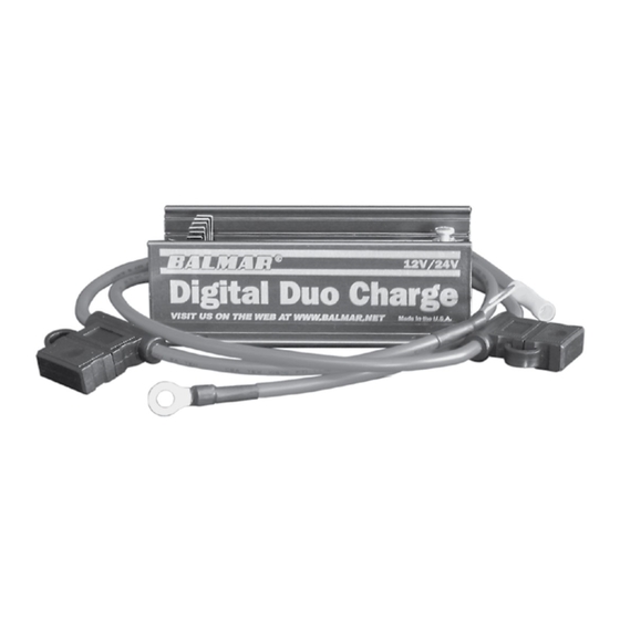
Digital Duo Charge
•
Input Cable (Includes two ring terminal connectors and 30-amp ATC fuse and fuseholder)
•
Output Cable (includes one ring terminal and one butt connector, with a 30-amp ATC fuse and fuseholder)
•
Programming screwdriver (magnetic tip at end of screwdriver handle is used for programming, not the blade end)
•
Instructional manual
Installation Basics
The Duo Charge MUST be mounted within the length of the Input Cable from the house battery. Four mounting holes are
included on the mounting tabs of the Duo Charge. Ensure that the mounting location is protected from moisture and tem-
peratures in excess of 120º F. The Duo Charge should be installed far enough from inverters, navigational, and communica-
tions equipment to ensure protection from radio frequency noise. The location of the Duo Charge should make it possible to
easily view its LED display. The short length of the Input Cable and longer Output Cable allow the wiring to act like an electric
spring, enabling the Duo Charge to address high battery loads more efficiently.
Wiring Basics
Once installed as described above, the Duo Charge can be wired for proper operation. The following sections will describe
the recommended connection points for optimal charging performance. The four following connections are required.
Ground Wire
The Duo Charge must be properly connected to system ground, which must be shared between the house and starting bat-
tery banks, for proper operation. Failure to do so will result in non-operation and potential damage to the device. Connection
to system ground can be made at one of the following: house battery negative post, starting battery negative post, or system
ground bus. User-supplied 14-gauge wire is recommended. To install the ground wire:
1.
Select a length of 14-gauge wire long enough to extend from the Ground Terminal
on the Duo Charge to your intended ground source, such as a ground bus as shown
at right.
2.
Crimp appropriately-sized ring terminal and 1/4" female spade connector to the
wire ends.
3.
Connect the female spade terminal to the Ground Terminal
on the Duo Charge.
4.
Connect the ring terminal to the desired ground source.
Output Cable
The Duo Charge includes a 30-amp, fused 10-gauge cable with
one ring terminal and a butt connector terminal. The installer
must supply the length of 10-gauge wire required to extend to the starting battery from the
butt connector end of the Output Cable. A minimum run of eight feet of wire from the Out-
put Cable to the starting battery is recommended. Again, the reason for the extra wire length
is to act like an electic spring which allows the Duo Charge to produce a higher current. To
install the Output Cable:
1.
Attach the Output Cable's ring terminal to the starting battery positive post.
2.
Determine the correct length of 10-gauge wire to extend from the Output Cable to the
Duo Charge. Connect at the butt connector. Attach a ring terminal connector at the end of
the 10-gauge wire and connect to the Duo Charge output terminal.
2