Balmar 97 Series Installatie- en bedieningshandleiding - Pagina 14
Blader online of download pdf Installatie- en bedieningshandleiding voor {categorie_naam} Balmar 97 Series. Balmar 97 Series 20 pagina's. Alternator
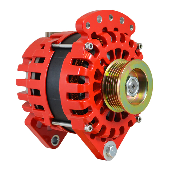
95-SERIES ALTERNATORS
Large case 95-Series alternators are designed to provide outputs of
165 or 210 amps at 12 volts, or 140 amps at 24 volts. Mounting is a
4"ID J-180 saddle-style mount. Alternators in the 95-Series feature iso-
lated ground terminals, external regulation and 12-pole stator output.
1. Positive Output Terminal - Must be connected, via properly-sized
cable to the battery or batteries being charged. Cable size is deter-
mined by alternator output and length of cable run. See Page 3 for
wiring size chart.
2. Negative Terminal (Ground) - Must be connected to system
ground via properly sized cable. Cable size is determined by al-
ternator output and length of cable run. See Page 3 for wiring size
chart.
3. Stator Output - Unrectified source of AC voltage which can be
used as a signal for an electric tachometer. In 12-volt systems, sta-
tor terminal will connect to WHITE wire. In 24-volt systems, the Sta-
tor Wire will connect to the ORANGE wire in the regulator wiring
harness.
4. External Field Terminal - Connects to external voltage regulator
via wiring harness.
5. Temp Sensor (Not Shown) - There is a tapped hole on the side of
the rear casing for the (Optional) MC-TS-A sensor. Do not bend the
heat shrink or ring terminal
An unsupported cable may damage the positive or negative terminals, result-
ing in damage to alternator, regulator and wiring. Ensure that cables are ad-
equately supported to supply strain relief.
97 EHD-SERIES ALTERNATORS
EHD-Series alternators are designed to provide outputs of 185 or 265
amps at 12 volts, or 190 amps at 24 volts. Mounting is a 4"ID J-180
saddle mount. Alternators feature case ground, external regulation and
12-pole stator output.
1. Positive Output Terminal - Must be connected via properly-sized
cable to the battery or batteries being charged. Cable size is deter-
mined by alternator output and length of cable run. See Page 3 for
wiring size chart.
2. Negative Terminal (Ground) - Must be connected to system ground
via properly sized cable. Cable size is determined by alternator out-
put and length of cable run. See Page 3 for wiring size chart.
3. Stator Output - Unrectified source of AC voltage which can be used
as a signal for an electric tachometer. In 12-volt systems, stator
terminal will connect to WHITE wire. In 24-volt systems, the Stator
Wire will connect to the ORANGE wire in the regulator wiring har-
ness. Any terminal can be used.
4. External Field Terminal - Connects to external voltage regulator
via wiring harness. NOTE: There are two terminals in the location
shown. One connects to the BLUE field wire from the regulator, the
other must be connected to the ground terminal.
5. Temp Sensor (Not Shown) - There is a tapped hole on the side of
the rear casing for the (Optional) MC-TS-A sensor. Do not bend the
heat shrink or ring terminal
An unsupported cable may damage the positive or negative terminals, resulting in damage to alternator, regulator and wiring. Ensure
that cables are adequately supported to supply strain relief.
1
Page
14
3
4
2
4
3
2
1