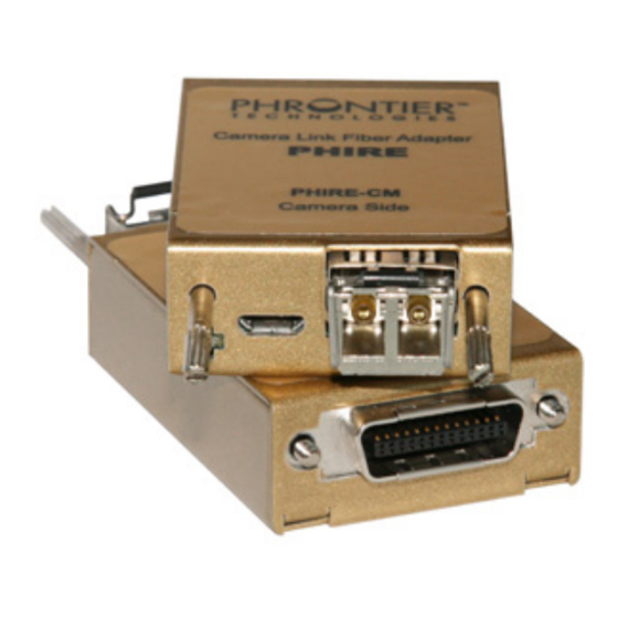
CAMERA LINK PHRONTIER PHIRE PHR-85-M025 Gebruikershandleiding - Pagina 2
Blader online of download pdf Gebruikershandleiding voor {categorie_naam} CAMERA LINK PHRONTIER PHIRE PHR-85-M025. CAMERA LINK PHRONTIER PHIRE PHR-85-M025 13 pagina's. Fiber adapters

TABLE OF CONTENTS
1. Introduction ........................................................................................................................... 3
2. Available Models ................................................................................................................... 3
2.1. Two fiber models with multimode fibers .......................................................................... 3
2.2. Two fiber models with single mode fibers ....................................................................... 3
2.3. Single fiber models (PHIRE-S series) ............................................................................. 4
3. Packing List ........................................................................................................................... 4
4. Installation ............................................................................................................................. 4
5. Functionality .......................................................................................................................... 5
5.1. DC Power Input Port ....................................................................................................... 6
5.2. Camera Link Port & PoCL compatibility .......................................................................... 6
5.3. LED Status Indicators ..................................................................................................... 7
5.4. Optical I/O Port ............................................................................................................... 7
5.5. Optical Fiber Cable ......................................................................................................... 8
6. Technical Specifications ........................................................................................................ 9
6.1. General Specification ..................................................................................................... 9
6.2. Camera Link Interface .................................................................................................... 9
6.2.1.
Two fiber models................................................................................................. 9
6.2.2.
Single fiber models (PHIRE-S series) ................................................................. 9
6.3. Optical Interface ............................................................................................................10
6.3.1.
Two fiber models................................................................................................10
6.3.2.
Single fiber models (PHIRE-S series) ................................................................10
6.4. Mechanical Dimensions .................................................................................................10
7. Trouble Shooting: ................................................................................................................ 11
8. Product Safety and Regulatory Compliance: ....................................................................... 12
8.1. Product Safety: ..............................................................................................................12
8.2. Regulatory Compliance: ................................................................................................12
9. Contact Us: ......................................................................................................................... 13
FIGURES
System Diagram ........................................................................................... 5
Figure 2 Electrical Connection of DC Input Connector (Front View) ........................................... 6
Figure 3 Optical fiber connection ................................................................................................ 8
TABLES
Table 1 Installation and Power up Steps for the PHIRE System ................................................. 5
Table 2 PoCL features and pin assignment on MDR26 plug ...................................................... 7
Table 3 LED Functionality Descriptions ...................................................................................... 7
Table 4 Trouble Shooting Procedures .......................................................................................12
D-A-CH
FrAnCe - Telecom
Phrontier Technologies
Laser 2000 GmbH
Laser 2000 SAS
82234 Wessling
78860 St-N. l. Bretèche
Tel. +49 8153 405-0
Tel. +33 1 30 80 00 60
www.laser2000.de
www.laser2000.fr
FrAnCe - Photonic
PHIRE User Manual V4
Laser 2000 SAS
33600 Pessac
Tel. +33 5 57 10 92 80
www.laser2000.fr
IberIA
norDICs
Laser 2000 SAS
Laser 2000 GmbH
28034 Madrid
112 51 Stockholm
Tel. +34 617 308 236
Tel. +46 8 555 36 235
www.laser2000.es
www.laser2000.se
2
