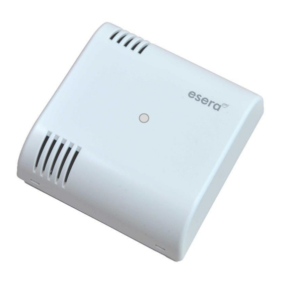
esera automation 11134 V2 Gebruikershandleiding - Pagina 3
Blader online of download pdf Gebruikershandleiding voor {categorie_naam} esera automation 11134 V2. esera automation 11134 V2 7 pagina's. Multisensor temperature, humidity and brightness for 1-wire bus system

Art. No. 11134 V2
3
Ambient conditions
Temperature,
operation
Air humidity
Dimensions
Protection class
Protection system
Auto-E-Connect
Support
4
Conformity
EN 50090-2-2
EN 61000-4-2, ESD
EN 61000-4-3, HF
EN 61000-4-4, Burst
EN 61000-4-5, Surge
EN 61000-6-1, Interference immunity
EN 61000-6-3, Interference radiation
RoHS
5
Connection diagram
The connection diagram is available in the store as a
separate document.
The Temperature and Humidity Sensor is connected by
screw terminals.
The pin assignment of the screw terminals is printed on the
printed circuit board.
Assignment
The Multisensor has to be supplied with three cables
(ground, 1-Wire Data and 5V). The parasitic mode is not
supported.
Note
The module may only be operated at the voltages and under the ambient conditions specified for it.
The modules may only be commissioned by a qualified electrician.
Please observe the specified operating position of the device.
For further information on the operating conditions, see the following instructions under "Operating
conditions".
Due to the high quality reverse polarity and overvoltage protection no parasitic operation is possible.
Note on brightness measurement
Please note that due to the positioning of light sources in relation to the angle of incidence of the
Multisensor, there may be considerable deviations in the measured brightness values of hand-held
brightness meters.
In the case of lighting with fluorescent or LED lamps, the value may also fluctuate. A living room brightness
control is usually impaired by strongly changing light conditions, e.g. by shadows of people in the room and
the resulting fluctuations of the sensor light values, and a well-functioning control function is often difficult to
implement. The reason for this is largely the unfavorable placement in the light switch area for the
brightness measurement of the Multisensor.
All rights reserved. Reproduction as well as electronic duplication of this user guide, complete or in part, requires the written consent of
ESERA GmbH. Errors and technical modification subject to change. ESERA GmbH 2021
www.esera.de
-30°C to 60°C
10 - 92% (non condensing)
71 x 71 x 32mm (LxWxH)
III
IP20
No Auto-E-Connect Support
11134-V2 V1.0 R1.0 Manual
MS 100
Multisensor
Page 3 of 7
