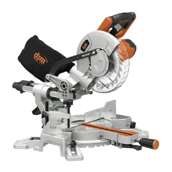
djm direct DJMSL8 Vertaling van de originele handleiding - Pagina 8
Blader online of download pdf Vertaling van de originele handleiding voor {categorie_naam} djm direct DJMSL8. djm direct DJMSL8 14 pagina's.

–Remove the flat washer, outer blade washer and the blade.
–Wipe a drop of oil onto the inner blade washer and the outer blade
washer where they contact the blade.
–Fit the new blade onto the spindle taking care that the inner blade
washer sits behind the blade.
–Replace the outer blade washer.
–Depress the spindle lock button (22) and replace the flat washer and
blade bolt.
–Use the 6 mm hex key to tighten the blade bolt securely (tighten in
an anti-clockwise direction).
–Lower the blade guard hold the rotating lower blade guard (8) and
blade bolt cover (10) in position and tighten the fixing screw to
secure the blade bolt cover inposition.
–Check that the blade guard operates correctly and covers the blade
as the saw arm is lowered.
–Connect the saw to the power supply and run the blade to make
certain that it is operating correctly.
Setting the Table Square with the Blade
– Make sure that the electrical plug is removed from the power
point.
– Push the saw arm (3) down to its lowest position and engage the
release knob (4) to hold the saw arm in the transport position.
–Loosen the mitre locks (20) and lifting up the mitrelatch (21).
–Rotate the table (16) until the pointer is positioned at0°
–Release mitre latch (21) and tighten the mitre locks(20).
–Loosen the bevel lock (12) and set the saw arm (3) at0°bevel (the
blade at 90°to the mitre table). Tighten the bevel lock (12).
–Place a set square against the table (16) and the flat part of the
blade.
–Rotate the blade by hand and check the blade-to-table alignment at
several points.
–The edge of the set square and the saw blade should be parallel.
–If the saw blade angles away from the set square, adjust as follows.
–Use a 10 mm wrench or adjustable wrench to loosen the lock nut
securing the 0° bevel adjustment screw (29). Also, loosen the bevel
lock (12).
–Adjust the 0° bevel adjustment screw (29) using a 4mm hex key to
bring the saw blade into alignment with the square.
–Loosen the Phillips head screw holding the pointer of the bevel scale
(13) and adjust the position of the pointer so that it accurately
indicates zero on the scale. Retighten the screw.
–Retighten the bevel lock (12) and the lock nut securing the 0° bevel
adjustment screw (29).
Setting the Fence Square with the Table
–Make sure that the electrical plug is removed from the power point.
–Push the saw arm (3) down to its lowest position and engage the
release knob (4) to hold the saw arm in the transport position.
–Loosen the mitre locks (20) and lifting up the mitrelatch (21).
–Rotate the table (16) until the pointer is positioned at0°
–Release mitre latch (21) and tighten the mitre locks(20).
–Using a 5 mm hex key, loosen the two screws securingthe fence (14)
to the base.
–Place a square against the fence (14) and alongside the blade.
–Adjust the fence (14) until it is square with the blade.
–Tighten the screws securing the fence (14).
–Loosen the Phillips head screw holding the pointer of the mitre scale
(17) and adjust it so that it accurately indicates the zero position on
the mitre scale.
–Retighten the screw securing the mitre scale pointer.
Setting the Cutting Depth
The depth of cut can be pre-set for even and repetitiveshallow cuts.
–Slide the stop plate (24) towards the front position.
–Loosen the lock nut (25) to free the lock knob (23),turn the stop
knob until the cutting head down until the teeth of the blade are at
the desired depth.
–While holding the upper arm in that position, tighten the lock nut to
secure the stop knob.
–Recheck the blade depth by moving the cutting head front to back
through the full motion of typical cut along the control arm.
10. Transport
1. Turn off the power tool before any transport and disconnect it
from the power supply.
2. Apply the power tool at least with two people, do not touch the
table extensions.
3. Protect the power tool from knocks, bumps and strong vibrations,
such as during transport in vehi-cles.
4. Secure the power tool against overturning and slid-ing.
5. Never use the safety devices for handling or trans-porting
purposes.
11. Maintenance
Warning! Prior to any adjustment, maintenance or service work
disconnect the mains power plug!
11.1 General maintenance measures
- Keep all safety devices, air vents and the motor hous-ing free of dirt
and dust as far as possible. Wipe the equipment with a clean cloth or
blow it down with com-pressed air at low pressure.
- We recommend that you clean the equipment imme-diately after
you use it.
7
