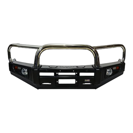
Dobinsons BU59-3660 & BU59-3510 Installatiehandleiding - Pagina 7
Blader online of download pdf Installatiehandleiding voor {categorie_naam} Dobinsons BU59-3660 & BU59-3510. Dobinsons BU59-3660 & BU59-3510 11 pagina's. Bullbar toyota hilux vigo 2005 - 2011

enough to reach the new bullbar
indicator/parker lights and extend if required.
Using the diagram at the end of this manual,
join the corresponding wires to original
vehicle wires located in the previous step. The
wires can be joined by either using good
quality snap lock crimp connectors or by
soldering. Ensure the connection is secure and
is sufficiently insulated.
12. While the head lights are out, remove the
original side bumper mounts. These are the
long black sections that support the bumper
near the wheel arch. Do this by removing the
bolt on the side, and then from inside the
guard unclip both clips to free the bracket..
13. Re-install both head lights once the wiring is
run and the bumper clips have been removed.
14. Fit the bulbar bracket to the chassis with the
hardware supplied as per the diagrams on
page 3 and 5 (there are 2 styles of brackets
used.. Ensure when tightening that the
bracket is central to the vehicle.
15. Carefully un-wrap the bulbar taking care not
to scratch it especially on the top loops.
Dobinsons Springs and Suspension
R
e
i
n
s
tall the number plate. If installing driving
lights to the bullbar it is easiest to install now.
16. If not installing a winch skip to step 24.
17. See the Installation section of your Dobinsons
4x4 Winch manual for specific detailed fitting
instructions. For a brief overview see the
following steps.
18. Test fit your winch to the mounting bracket
and do up loosely with the clutch handle on
the left hand side of the vehicle.
19. This may require the clutch handle and gear-
box housing to be rotated forward one or 2
bolt holes to allow easy access through the
bulbar holes. See instructions in winch user
manual.
20. Determine where the winch control box will
be located and mount the control box. See
instructions in winch user manual for control
box mounting options. If mounting to the top
of the bullbar using the supplied bracket,
check clearance of control box to grill and also
check where the wires will route as if the
wires are passing through the holes in the top
of the bullbar the control box may not be able
to be wired until the bullbar has been fitted as
below.
21. Wire the winch up as per the winch
instruction manual and bolt the winch to the
mounting bracket, ensure the mounting bolts
are not too long and tighten correctly. Route
the wires and connect to battery and also
route the breather hose.
22. Unwind some cable from the winch, and pass
the cable through the fairlead hole in the
bullbar and through the roller fairlead. This
may require removing a circlip from the
fairlead and re installing once the cable is
passed through.
23. Install the roller fairlead into the bulbar.
24. Check the poly bulbar over riders, fog light
and top loop bolts are tight (Do not over
tighten the stainless steel loop mounting
bolts. Do not over tighten the poly bullbar
www.dobinsonsprings.com
