Clinton Electronics CE-M21A-PIR Handleiding basisinstellingen
Blader online of download pdf Handleiding basisinstellingen voor {categorie_naam} Clinton Electronics CE-M21A-PIR. Clinton Electronics CE-M21A-PIR 7 pagina's. Pvms w/ axis m3065
Ook voor Clinton Electronics CE-M21A-PIR: Handleiding basisinstellingen (9 pagina's)
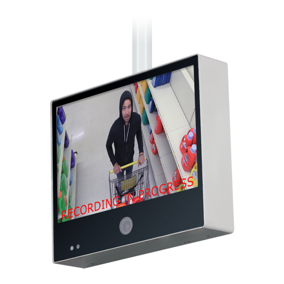
Basic Setup Guide: 21", 27" & 32" IP PVMs with Axis M3045 Camera
CE-M21A-PIR / CE-M27A-PIR / CE-M32A-PIR
Remove Cover Plate and Install PVM:
1
Remove the cover plate on the back-side of the PVM
and set aside. Install the PVM to desired VESA mounting
bracket following instructions supplied with the mount.
*Mounting Bracket Not Included, Sold Separately.
Connect DC24V Power:
2
Connect DC24V power to PVM (using the supplied
pigtail adapter cable) or AC110V (32" models only). It is
recommended that the power supply not be plugged into
the main power source during this step *Power Supply
Not Included, Sold Separately.
Connect Network:
3
Connect an ethernet cable to the port marked LAN.
To view the IP camera on the network follow the setup
instructions from the included IP camera software. This
device does not support PoE connection.
Turn Power ON:
4
After making the power and network connections, plug the power supply into a wall outlet. Connecting the
DC24V pigtail into the PVM while plugged into the main power source can cause sparking.
Camera Boot-Up:
5
Colored bars will display on the screen while the Axis IP camera is booting up. These bars will be on the screen
for approximately 20-30 seconds.
Camera Angle Adjustment:
6
If the camera appears to be slightly rotated the
angle might need to be adjusted. To adjust remove the 2
screws on the camera access door. Then turn the front of
the camera left/right until straight. Align the notch on the
front of the camera to the notch on the camera housing.
• This is not a PoE device.
• This device does not support WiFi
• 32" models: DO NOT CONNECT DC24V & AC110V POWER SIMULTANEOUSLY. Connecting both will cause
damage to the device.
Basic Setup Guide: CE-M21A-PIR / CE-M27A-PIR / CE-M32A-PIR
02.08.19
24V POWE R SUP PLY REQU IRED . S OLD S EPARATE LY
DC24V
DC24V
LAN
ANALOG
OUTPUT
Camera Access Door
Front Notch
Housing Notch
Information in this document is subject to change without notice.
1
Ethernet
HDMI
ALARM
POWER
AUTO
UP
DOWN
MENU
VESA Mounting Holes
Align 2 Notches