dol sensors 20R Technische gebruikershandleiding - Pagina 3
Blader online of download pdf Technische gebruikershandleiding voor {categorie_naam} dol sensors 20R. dol sensors 20R 4 pagina's. Capacitive sensor

LED indication
LED ON
4 User Guide
When there is material in front of the sensor, the output is in the reference position NO. When the material dis-
appears, the timer, starts, and the output will change to NCafter the set delay.
The status of the sensor is indicated with a yellow LED.
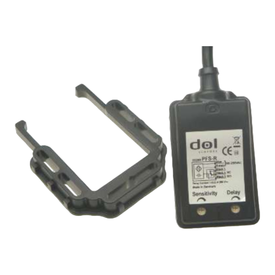
The sensor sensitivity and delayed disconnection can be adjusted on two trimmers.
Relay activated (NC) Relay in default position (NO)
Sensor
LED
NC
Contact
NO
5 Maintenance
If the sensor is located in a particularly dirty environment, it may be necessary to clean the area around the
sensor.
Otherwise, no additional maintenance is required.
6 Technical data
Electrical
Rated voltage (Ue)
Frequency
Consumption (max.)
Rated relay current at 250
V AC
Time delay, start-up
Time delay OFF
Time delay ON
Indication for output ON (if
installed)
DOL 20R
Sensor status
Relay activated (NC) – output OFF
Delayed disconnection:
fixed delay or delay can be adjusted on the trimmer.
Delayed connection:
fixed delay or delay can be adjusted on the trimmer.
Sensitivity:
fixed distance or Distance can be adjusted on the trimmer.
MaxRun-timer:
DOL 20R Settings on the trimmer: Off, Period 1, Period 2
ON
OFF
ON
OFF
V AC
Hz
W, 230 V AC
A RMS
A RMS
ms
s
s
www.dol-sensors.com
90-250
50-60
0.9
0.5, Inductive
1, Resistive
< 300
0-600*
1*
Yellow LED
Technical User Guide
3
