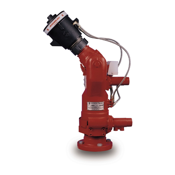
Akron Brass Genesis 3590 Gebruikershandleiding - Pagina 2
Blader online of download pdf Gebruikershandleiding voor {categorie_naam} Akron Brass Genesis 3590. Akron Brass Genesis 3590 8 pagina's.

GENESIS™ STYLE 3590 OWNER'S MANUAL
Introduction
The Akron Brass Genesis Style 3590 Manual Hydraulic Power Unit is designed to provide efficient trouble-free operation for many years. This manual
includes all the installation, operating and trouble-shooting instructions normally required to assist in obtaining the best possible performance from this
unit.
DO NOT attempt to install, operate or trouble-shoot this unit without first reading the warnings, installation, operating and trouble-shooting sections of
this manual.
General Product Description
This Genesis Style 3590 Manual-Hydraulic Power Unit provides manual; remote operation of a hydraulically controlled monitor, by means of a manual
hydraulic pump and three function control valves. The unit controls the horizontal, vertical movement of the monitor, plus the pattern of the nozzle. The
speed of each function is directly proportional to the stroke rate of the pump handle. The major components of the Genesis Style 3590 power unit in-
clude a double-acting hydraulic piston pump, a three spool directional control valve with integral pressure relief, and a 5.4 gallon hydraulic fluid reservoir,
all combined into an efficient compact system.
Warning
1.
This unit is designed to operate in ambient temperatures of minus 10 degree F (-10 degree F) to plus
140 degree F (140 degree F). DO NOT install this unit in an environment where ambient temperatures of less than
minus 10 degree F (-10 degree F) or more than plus 140 degree F (140 degree F) are possible.
2.
This unit is equipped with a fixed (non-adjustable) pressure relief valve, set at 1000 psi. DO NOT attempt to make
adjustments to this valve.
3.
Use only the recommended hydraulic fluids listed in this manual. Use of improper hydraulic fluids can result in
poor monitor response especially in cold conditions. Use of improper hydraulic fluids can also result in damage
to internal seals leaving the unit inoperative.
4.
This size of the interconnect tubing/hose between the monitor and the power unit is a function of the viscosity
of the selected hydraulic fluid, the ambient temperature, and the distance between the units. If the distance
between the monitor and the power unit is less than 100 feet one way; 1⁄2" diameter tubing is normally sufficient.
Distances beyond 100 feet will require a corresponding increase in tubing diameter. If you have questions
concerning the determination of the optimum tubing size for your installation, contact Akron Brass for
assistance.
Installation And Start-Up
The Akron Brass Manual-Hydraulic Power Unit is delivered preassembled and tested to assure ease of installation and operation. A mounting bracket is
also included which will securely attach the power unit to a 4" to 6" diameter standpipe.
After attaching the mounting bracket to a suitable standpipe, and the power unit to the bracket; as shown in the accompanying installation drawing, the
customer supplied hydraulic interconnect piping which runs between the power unit and the monitor can be installed. Again, referring to the installation
drawing, connect piping between ports as shown ("A" to "A", "B" to "B" etc.). Ensure that all pipe fittings which terminate at the power unit or monitor are
of the proper type and size (o-ring, NPT etc.).
After the system is installed and piping interconnections are completed the power unit reservoir should be filled to the top with the proper grade of
hydraulic fluid. (See the specifications sections of this manual for recommended hydraulic fluids.)
Prior to placing the unit into operation, all entrapped air must be purged from the system. This can be accomplished by completing each of the following
steps for each of the six hydraulic lines. Remember, purge only one line at a time.
1.
Shift the function control lever, located on the valve bank, to the "on" position for the line which is to be purged.
2.
Go to the highest hydraulic connection for that line (usually at the monitor) and disconnect it.
3.
Using a suitable container to catch oil from the disconnected line, have an assistant pump the hand pump lever
until a solid stream (no air bubbles) of hydraulic fluid is pumped into the can. During this process, have the
assistant monitor the level of the hydraulic fluid in the reservoir. If the fluid level drops below the bottom level of
the sight glass stop and refill the reservoir before continuing.
4.
Once a solid stream of oil is observed coming from the disconnected pipe, stop the process, reconnect the pipe
and repeat this procedure with the pipe of the functions opposite member, i.e.; do both pipes for the rotation
function before moving onto the elevation or pattern functions.
5.
Repeat steps 1-4 for the remaining two functions.
After the entire purging process is complete, ensure that all connections are tight and leak free. Remove or add hydraulic fluid to reservoir as required to
maintain a level which is approximately 2⁄3 up the sight glass
2
