Blueprint HUB-4 Instructies - Pagina 2
Blader online of download pdf Instructies voor {categorie_naam} Blueprint HUB-4. Blueprint HUB-4 3 pagina's.
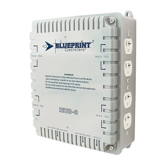
HUB-4
Main Power Requirements
• A main power source must be supplied for the unit to function.
• Verify main power source has the same voltage and amperage
ratings as the equipment being controlled by the HID hub (see
Specifications section).
• Main power must be hardwired into the circuit breaker panel.
• Use only the main circuit breaker and wire with the specified
ratings to provide the main power (240-volt ratings noted in
Specifications section).
• Proper connection of the ground wire to the ground terminal is
critical for safe operation.
• All connected ballasts MUST be wired correctly and according
to the main power voltage.
o 240-volt main power requires ballasts wired for 240 volts.
o 120-volt main power requires ballasts wired for 120 volts
(HUB-4 and HUB-8 units only).**
**The universal 120-volt/240-volt receptacles can be used to
operate 120-volt devices ONLY if the main power is also wired
in at 120 volts. Consult an electrician for 120-volt installation.
Connecting a 120-volt ballast to a unit with 240-volt main power
could result in damage or fire. Consult the ballast manufacturer
for any questions concerning the electrical requirements.
Note: Be aware that amperage draw at 120 volts is
significantly higher than at 240 volts. For example, running
four 1,000-watt, 120-volt ballasts on one unit (HUB-4) or relay
of four outlets (HUB-8) will exceed the maximum load of 30
amps per unit or relay. Only operate as many 120-volt ballasts
as capable taking into consideration the circuit wiring, main
breaker, and component wiring max. amperage ratings.
Installation
Disconnect all power prior to installing this unit. DO NOT
connect ballasts to the HID hub until AFTER the main power is
properly installed.
Main Power
Connections
Ground Terminal
Hardwire Trigger
Cable Connection
Green LED "ON"
Indicator Light
Cable Clamp
Main Power Connection
1. Using a Phillips-head screwdriver, remove each of the four
screws securing the front cover to the back casing.
2. Feed the properly rated main power cable through the cable
clamp and tighten the clamp to secure the cable in place.
3. Insert the green or bare ground wire into the grounding
terminal and secure.
4. Strip the insulation from the main power wires. Insert each
bare wire end into the corresponding connection point on the
power relay (marked "main power connections").
5. Tighten the screws by hand using a flat head screwdriver.
Torque the main power connections on the relay to 40 lb-in
on the HUB-4 model, or torque the terminal block to 30 lb-in
on the HUB-8 model. DO NOT USE AN ELECTRIC DRILL
AS IT CAN OVERTIGHTEN AND BREAK THE
CONTACTOR TERMINAL.
6. Reinstall the front cover, being careful not to overtighten as it
can break the plastic housing.
7. Connect the main power connections to the properly rated
circuit breaker in the main panel.
Trigger Cable Testing
DO NOT plug any ballasts into the HID hub during this
testing procedure.
1. Plug the trigger cable into an active 120-volt timer
or controller.
2. The main relay will close and produce a distinct click when
the trigger cable is connected and the external timer or
controller is ON. The green LED will also illuminate.
3. Once trigger cable functionality is confirmed, unplug the
trigger cable from the external timer or controller. The green
LED will turn OFF.
Ballast Connection
1. Verify trigger cable is disconnected from the external timer
or controller (the timing device should remain plugged into
a 120-volt power source).
2. Plug ballast power cords into the receptacles of the
HID hub.
3. Connect the trigger cable to the external timer or controller.
The trigger cable MUST be connected to an external timing
device or controller providing 120-volt power to the main
relay for the unit to operate.
HUB-8