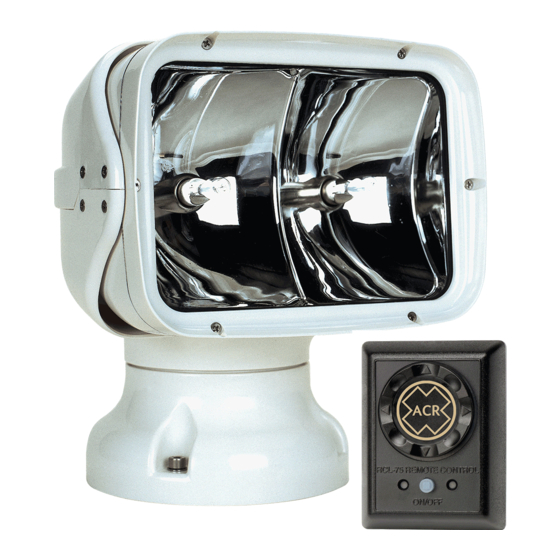
ACR Electronics RCL-75 Handleiding productondersteuning - Pagina 8
Blader online of download pdf Handleiding productondersteuning voor {categorie_naam} ACR Electronics RCL-75. ACR Electronics RCL-75 20 pagina's. Remote control searchlight system
Ook voor ACR Electronics RCL-75: Handleiding productondersteuning (15 pagina's), Handleiding productondersteuning (20 pagina's)

CAUTION: The connectors on each side of the wire harness are
different. Test fit connector to switch before running the harness to the
light.
For ease of installation, a 17-foot (5.18 meter) wiring harness to connect
the remote control to the light has been supplied. The wire should be
run from the Point Pad™ to the light. Do not run wire near sharp edges.
When passing through bulkheads, use a cable outlet (available at
marine hardware stores). After the cable has been run, the remote
control is ready to be connected.
The light needs to be connected to a power source. It is recommended
to use 14 AWG for this installation. The positive lead should be
connected to a 15 amp fuse. For wire runs over 16 feet (4.88 meters),
use 12 AWG.
Precautions should be taken to make power connections as watertight
as possible.
Point Pad™ Options
Make sure area is clean and dry. Use templates for marking drill hole
pattern. Verify that the drill holes will not impact or harm other items
(wires, plumbing, hardware, bulkhead).
The URP-102 Point Pad™ is supplied as a surface mount unit (see
figure 4). A flush mount option is provided (see figure 5). To switch
mounting options, unscrew the six (6) screws on the unit's back plate
and remove the front cover. Fit the Point Pad™ with the flush mount
cover, replace the back plate, and screw the unit back together.
Mounting the Point Pad™
Both the surface mount and flush mount options require access to the
backside of the mounting location. Make sure there are no obstructions
behind the area where the switch is to be located (e.g. bulkheads, wires,
plumbing, or hardware). Check in advance that the coax cable from the
Master Controller can be routed to this location. Generally, the Point
Pad™ should be mounted in a protected area.
Install the surface mount Point Pad™ by drilling 3 holes in the
dashboard location using the Point Pad™ Surface Mount Template
supplied in the Mounting Templates. Mount the Point Pad™ to the
dashboard using the gasket, washers, and nuts supplied. Use a sealant
around the bolt holes to protect from moisture intrusion.
Y1-03-0158H
7
