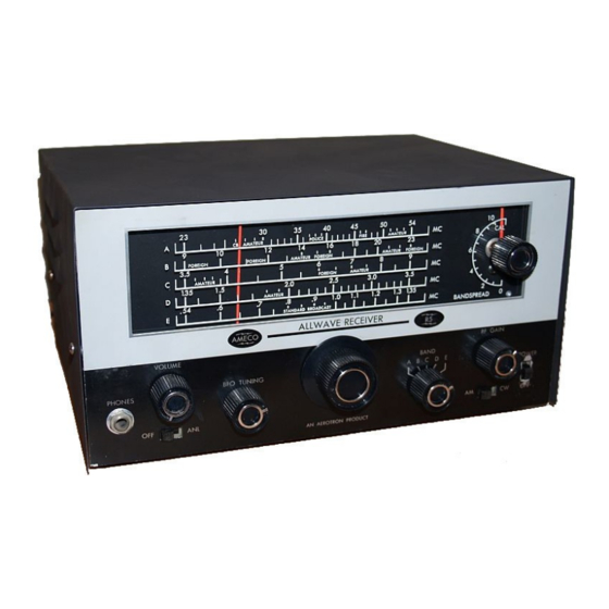
Ameco R-5 Instrukcja obsługi - Strona 9
Przeglądaj online lub pobierz pdf Instrukcja obsługi dla Odbiornik Ameco R-5. Ameco R-5 17 stron.

ALIGNMENT PROCEDURE
1. Use an amplitude modulated generator covering 455 kHz to 54 MHz.
2. Connect the output meter across the speaker voice coil.
3. Use non-metallic alignment tools. GC #8606L or similar.
4. Use a standard EIA dummy antenna as shown.
5. VOLUME control near maximum clockwise.
BANDSPREAD control at 10.
AM-CW switch at AM
OFF-ANL switch in OFF position.
RF GAIN at maximum unless noise exceeds 50 mW with no signal or an unmodulated signal.
6. Refer to Outline Diagram for location of adjustments.
7. Bottom must be on chassis.
STEP
SIGNAL
GENERATOR
CONNECTIONS
1.
High side through a
0.01 uF capacitor to
stator plate of rear
section of TUNING
capacitor.
2.
High side through a
0.01 uF capacitor to
stator plate of rear
section of TUNING
capacitor. Modulation
OFF.
3.
High side through EIA
antenna to ANT
terminal on rear of
chassis. Low side to
chassis.
9
GENERATOR
FREQUENCY
SELECTOR
455 kHz
E
(30% mod.)
455 kHz
E
1.3 MHz
E
(30% mod.)
BAND
RECEIVER
DIAL
SETTING
SETTING
0.54 MHz
0.54 MHz
1.3 MHz
ADJUSTMENT
L3, top and bottom
of T2, T3, T4 for
maximum output.
Keep reducing the
generator output to
keep output meter
below 50 mW.
Tune BFO to zero
beat. Adjust knob so
pointer aims straight
up and tighten set
screw.
C107E and C105E
for maximum output
as in Step 1.
