Barksdale L1X Instrukcja obsługi - Strona 6
Przeglądaj online lub pobierz pdf Instrukcja obsługi dla Przełącznik Barksdale L1X. Barksdale L1X 8 stron. Mechanical temperature switches
Set point adjustment
In temperature switches, the liquid expands in the sensing element (capillary) when the temperature
changes. Due to the expansion the micro switch is actuated.
Upon delivery of the product, the set points are likely to be found in the middle of the adjustable
range. On request, fix set points may be adjusted by our factory. In this event, the point will be
indicated on the type plate or any separate plate, i = increasing, d = decreasing.
The set point is adjusted by turning the adjustment knob. (Knob visual indication is for reference
only).
IMPORTANT
In some cases the corresponding housing cover must be removed in order to reach the
adjustment knob.
Heat the temperature switch to the desired switching temperature.
Turn the adjustment knob to actuate the micro switch. (Knob visual indication is for reference
only)
IMPORTANT
Please consult the wiring diagram for the contact status at state of rest (see Fig. 5).
Precise adjustment of set point to actuate on increasing temperature
Connect a control unit (lamp, buzzer, etc.) to (C) and (NO). When the unit is connected
correctly and the sensor temperature is higher than the temperature adjusted on the scale, the
buzzer or lamp is not activated.
Adjust the desired switch point with the help of the scale via the adjustment knob. (Knob visual
indication is for reference only).
Watch the switch point while the temperature is rising (about 2°C/minute). The control unit is
activated when the switch point is reached.
If necessary, re-adjust the set temperature by some degrees (by means of the scale the
temperature can be adjusted with an accuracy of 3...5 % of the scale value).
Precise adjustment of set point to actuate on decreasing temperature
Connect a control unit (lamp, buzzer, etc.) to (C) and (NC). When the unit is connected correctly
and the sensor temperature is higher than the temperature adjusted on the scale, the buzzer or
lamp is activated.
Adjust the desired switch point with the help of the scale via the adjustment knob. (Knob visual
indication is for reference only).
Increase the temperature (about 2°C/minute) until the control unit is deactivated.
Watch the point at which the control unit is activated again while the temperature is falling. This is
the set switch point.
If necessary, readjust the set temperature by some degrees (by means of the scale the
temperature can be adjusted with an accuracy of 3...5 % of the scale value).
6
Buy: www.ValinOnline.com | Phone 844-385-3099 | Email: [email protected]
4 (0.16)
½" NPT
Ground screw
Optional adjustable
hysteresis (RD)
½" NPT
11 (0.43)
Contacts: color code and function
C
= Common
= purple
NC = Normally Closed Contact
= blue
NO = Normally Open Contact
= red
ø14.5 (0.43)
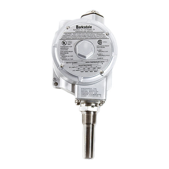
Fig. 10:
Temperature switch type ML1H-...
1212
Adjustment knob
19
35
(0.75)
(1.38)
70 (2.76)
48.5 (1.91)
28 (1.1)
11