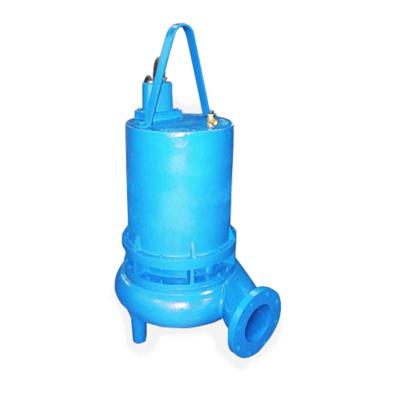
Barmesa Pumps 6BSE-HLDS Series Instrukcja instalacji, obsługi i konserwacji - Strona 10
Przeglądaj online lub pobierz pdf Instrukcja instalacji, obsługi i konserwacji dla Pompa wodna Barmesa Pumps 6BSE-HLDS Series. Barmesa Pumps 6BSE-HLDS Series 19 stron. Submersible solids handling pumps

Wear
Ring
-
Apply
compound to the bore of volute (37)
and press wear ring (33) into bore
until seated.
Impeller and Volute - Install impeller
(32) by appling a thin film of oil to
motor shaft and slide impeller
straight onto shaft, keeping keyways
lined up. Drive key into keyway.
Locate washer (34) and lockwasher
(10), apply thread lock primer (such
as Loctite® Primer T), let set per
manufacturer's
directions.
thread locking compound to threads
on cap screw (35), and thread into
shaft and torque to 35 ft/lbs.
barmesa.com
Place gasket (36) on volute and install
impeller and motor assembly over
studs and onto volute (37). Apply
thread locking compound to threads
of studs (31) and thread nuts (16)
onto studs and torque to 24 ft/lbs.
Check
for
binding
impeller. Clearance between the
impeller and volute should be
approximately 0.012 inch.
THREE-PHASE 230V AC
G L1
L2
G T1 T7 T2 T8 T3 T9 T4 T5 T6
MOTOR LEADS
Figure 5
Cable
Motor Lead Number
Green
Black
Red
White
4, 5 and 6 together
retaining
Apply
by
rotating
L3
Cable
Green
Black
Green
White
1 and 7
2 and 8
3 and 9
THREE-PHASE 460V AC
G
G
L1
L2 L3
G
T1
T2 T3 T4 T7 T5 T8 T6 T9
MOTOR LEADS
Figure 5
Motor Lead Number
Green
1
Red
2
3
4 and 7 together
5 and 8 together
6 and 9 together
Service
CONTROL CABLE
TEMPERATURE
MOISTURE
SENSOR
SENSOR
G
L1 L2
L3 L4
G
P1 P2
S1 S2
THERMOSTAT
N/C
N/O
Figure 5
Control Cable
Lead Number
Black
L1 (Temperature)
White
L2 (Temperature)
Red
L3 (Moisture)
Orange
L4 (Moisture)
Green
Ground
9
