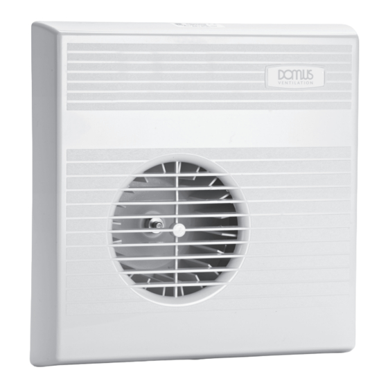
Domus MTT 070B Instrukcje instalacji - Strona 3
Przeglądaj online lub pobierz pdf Instrukcje instalacji dla Wentylator Domus MTT 070B. Domus MTT 070B 4 stron. Mayfair wall/ceiling fan

SURFACE MOUNTED
For installation on either wall or ceiling, follow the same procedures as frame mounted fans with the exception that the discharge
duct needs to be flush with the surface of the inside wall or ceiling, to meet up with the discharge outlet of the surface mounting
box.
Please refer to the following pages for relevant wiring diagrams. When fitting into surface mounting box it is necessary to remove
the fan motor cover. To do this, remove the motor cover retaining screw. Ease front cover clear of the two clips. The motor cover
may be discarded.
To fit the fan into the surface mounting box, first remove it's front cover. This is retained by a screw on the bottom edge. Enter
the electrical contact pins and discharge spigot into their sockets and push gently into position. Retain the fan with four 6mm
screws supplied. Refit front cover.
Wiring Installation
WARNING: ISOLATE ELECTRICITY SUPPLY BEFORE COMMENCING WORK
WIRING REQUIREMENTS FOR DOMESTIC ELECTRIC FANS
It is recommended that fans be connected into the lighting circuit (see caution note on page 10) with double pole (3mm) isolation,
provided before the room light switch and suitably fused, in accordance with I.E.E. Regulations.
Wall and ceiling mounted fans for fixed wiring should be connected to the power supply via a cable with solid conductors of 1 to
1.5mm
only.
2
IF IN DOUBT CONSULT A QUALIFIED ELECTRICIAN
IMPORTANT
Surface mounting box (FLA 106A) and flat duct systems are manufactured from sheet metal and therefore require earthing.
NOTE
The Mayfair 2000 extractor fan and its mounting systems (with the exception of the above) are double insulated and do not require
earthing. The mounting system is provided with an earth termination for convenience only.
OPERATING SWITCH
ISOLATOR SWITCH
S/L
S/L
N
N
ISOLATOR SWITCH
L
L
N
N
Models
MSS 070B
FRAME TERMINALS
S/L = SWITCH LIVE
N = NEUTRAL
Models
MPC 070B
MIR 070B
FRAME TERMINALS
L = LIVE
N = NEUTRAL
A guide to
A guide to Ventilation
Ventilation
WHERE TO SITE YOUR FAN
Incorrect siting of an extractor fan can se-
verely impair its efficiency. It is therefore
important that the fan is correctly sited
using the following principles:
•
To ensure maximum air flow through
the whole room, mount in the wall or
ceiling furthest from the air inlet point
and at high level.
•
Do not position a fan where tempera-
tures are likely to exceed 40ºC.
•
When installing in a room with an
open fire or stove without a balanced
flue, ensure that there is sufficient
replacement air to prevent the fan
drawing air back down the flue.
•
A 230 Volt fan installed in a bathroom
must not be within reach of a person
using the bath or shower.
•
Always use an in-Duct or Low Voltage
Fan (SELV) to ventilate a shower cubi-
cle
WARNING:
Positioning the fan unit must be so as to
avoid the back flow of gases from open
flue or other open fire appliances.
Also to prevent combustion gases enter-
ing the air inlet, the air inlet must not be
positioned above or within 1
/
metres of
1
2
a combustion flue vent.
NOT FOR USE IN SHOWER CUBICLES OR ABOVE BATHS FITTED WITH A SHOWER.
MAX ROOM TEMPERATURES 40ºC
Building Regulation Requirements
Room
Extract Rate
Bathroom/shower room
54m
h (15 l/s)
3
with or without toilet
Toilet
21.6m
h (6 l/s)
3
Non domestic sanitary
21.6m
h (6 l/s)
3
accommodation (and/or
per w/c or 3 air
washing facilities)
changes per hour.
Rooms without opening windows require fans
to be fitted with 15 minute overrun timers.
