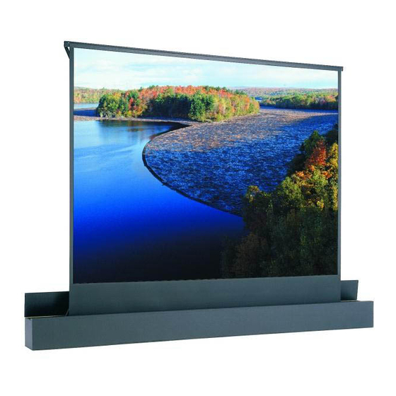
Da-Lite ASCENDER ELECTROL Instrukcja obsługi - Strona 4
Przeglądaj online lub pobierz pdf Instrukcja obsługi dla Ekran projekcyjny Da-Lite ASCENDER ELECTROL. Da-Lite ASCENDER ELECTROL 8 stron.
Również dla Da-Lite ASCENDER ELECTROL: Instrukcja obsługi (8 strony), Instrukcja obsługi (6 strony)

Ascender Electrol® Installation
WARNING: To prevent electrical shock or damage to the low voltage control (LVC), do not apply power to the LVC until all
connections are complete. Make sure power is turned off on all wires before making connections.
AVERTISSEMENT: pour éviter tout choc électrique ou d'endommager le tableau de contrôle basse tension, n'alimentez ce dernier
qu'une fois tous les branchements effectués. Vérifiez qu'aucun câble n'est alimenté avant d'effectuer les branchements.
LOW VOLTAGE CONNECTIONS:
Wall Switch
1.
Install wall switch where desired.
2. Use 2-conductor 20-24 gauge wire to extend the switch wire to
the required length.
3. Connect the wire from the switch to the wire labeled "wall switch".
Refer to Figure 3.
CAUTION: Never apply voltage to the wall switch lead or the
LVC will be damaged.
ATTENTION: N'appliquez jamais une tension aux fils du
commutateur mural sinon le tableau de contrôle basse
tension sera endommagé.
Control Panel
A control panel may be connected to the LVC by using the wall
switch wire lead. The control panel must provide a momentary,
dry contact closure of at least 1/2 second.
1.
Use 2-conductor 20-24 gauge wire to connect the control panel
to the wall switch lead.
2. A momentary closure when the screen is down will be an "up"
command.
3. A momentary closure when the screen is fully extended will be a
"down" command.
4. A momentary closure while the screen is in motion will be a "stop"
command.
CAUTION: Never apply voltage to the wall switch lead or the
LVC will be damaged.
ATTENTION: N'appliquez jamais une tension aux fils du
commutateur mural sinon le tableau de contrôle basse
tension sera endommagé.
4
120V/240V Connections:
AC Power Source
1.
Refer to Figure 3 for electrical connections. Wiring designated as
external is to be completed by installer conforming to local and
national codes.
NOTE: Must be installed in accordance with the requirements
of the Local Building Codes, the Canadian Electrical Code
(CEC), CAN/CSA C22.1 and the National Electric Code (NEC),
NFPA 70. An appropriate disconnect device shall be
provided as part of the building installation.
2. Use 14-18 gauge wire to connect power to the LVC wires labeled
"AC power input". Refer to Figure 3.
3. Connect the building ground wire to the ground lug on the metal
housing.
Optional Wireless Remote Connections:
Radio Frequency Remote
1.
Remove the center cover plate of the LVC box.
2. Route the receiver wire through the round plastic bushing and
plug it into the onboard socket marked "EYE". Refer to Figure 3.
Infrared Remote
1.
Remove the center cover plate of the LVC box.
2. Route the receiver wire through the round plastic bushing and
plug it into the onboard socket marked "EYE". Refer to Figure 3.
