Ekinex KNX EK-FB1-TP Skrócona instrukcja obsługi - Strona 2
Przeglądaj online lub pobierz pdf Skrócona instrukcja obsługi dla Kontroler Ekinex KNX EK-FB1-TP. Ekinex KNX EK-FB1-TP 4 stron. Binary output 8-fold 10a

1
2
3
1
2
3
4
5
6
7
8
C1
C2
C3
C4
0N
0N
0N
0N
0FF
0FF
0FF
0FF
C1
C2
C3
C4
EK-FB1-TP
8xD.O. 10A/230Vac
~
50/60 Hz
bus KNX
4
5
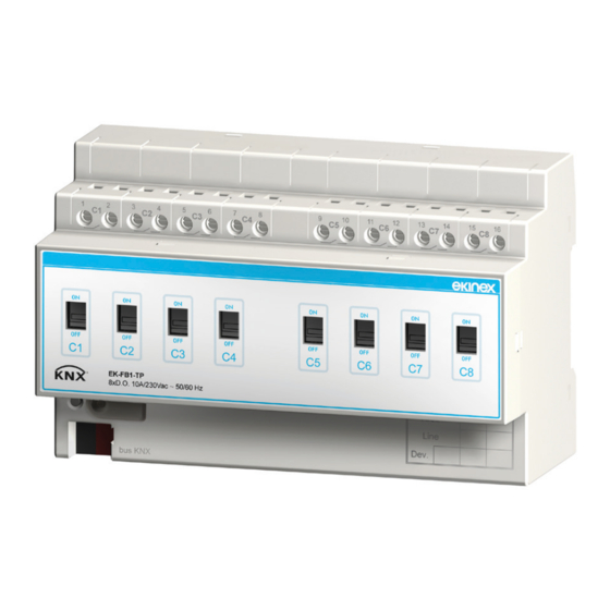
1) Terminal blocks for output channels
2) Lever switches for manual operation and status feedback
3) Programming pushbutton
4) Programming LED
5) Terminal block for KNX bus line
i
Note. In case of failure of the bus voltage, the
switching of the loads is possible only if they are still
powered with the mains voltage 230 Vac. The relay
status in case of failure and reset of the bus can be
set during the device configuration.
Display elements
• Red LED for displaying the active operating mode of
the device (on = programming, off = normal operation)
• Switches for displaying the status of the outputs (lever
up = closed contact, lever down = opened contact)
Lever in lower position (OFF):
relay contact opened
Mounting
The device has degree of protection IP20, and is there-
fore suitable for use in dry interior rooms. The housing is
made for rail mounting according to EN 60715 in boards
or cabinets for electrical distribution. The installation is in
horizontal position, the correct position is when the KNX
bus terminal is located at the bottom and the terminals for
the outputs are located at the top. For the installation of
the device on the rail proceed as follows:
• with the aid of a tool bring the locking device in the fully
lowered position (1);
• place the upper edge of the rear inner profile on the
upper edge of the rail (2);
• rotate the device towards the rail (3);
• push the locking device upward until it stops (4).
Before removing the device, be sure the inputs have been
9
10
11
12
13
14
15
16
C5
C6
C7
C8
0N
0N
0N
0N
0FF
0FF
0FF
0FF
C5
C6
C7
C8
Lever in upper position (ON):
relay contact closed
disconnected and the bus terminal has been extracted
from its slot. Use a screwdriver to slide down the locking
device and remove the device from the rail.
1
3
i
Note. It is recommended that the installation of the
device always ensure the full accessibility of the
front side to allow the operation of the pushbuttons.
.
Connection of the KNX bus line
The connection of the KNX bus line is made with the ter-
minal block (black/red) included in delivery and inserted
into the slot of the housing.
Characteristics of the KNX terminal block
• spring clamping of conductors
• 4 seats for conductors for each polarity
• terminal suitable for KNX bus cable with single-wire
conductors and diameter between 0.6 and 0.8 mm
• recommended wire stripping approx. 5 mm
• color codification: red = + (positive) bus conductor,
black = - (negative) bus conductor
1
2
3
4
5
6
7
C1
C2
C3
0N
0N
0N
0FF
0FF
0FF
C1
C2
C3
EK-FB1-TP
~
8xD.O. 10A/230Vac
50/60 Hz
bus KNX
+
-
!
Warning! In order to supply the KNX bus lines use
only a KNX bus power supply (e.g. ekinex EK-AB1-
TP or EK-AG1-TP). The use of other power supplies
can compromise the communication and damage
the devices connected to the bus.
2
2
4
8
9
10
11
12
13
14
15
C4
C5
C6
C7
C8
0N
0N
0N
0N
0N
0FF
0FF
0FF
0FF
0FF
C4
C5
C6
C7
C8
Bus
KNX
16
