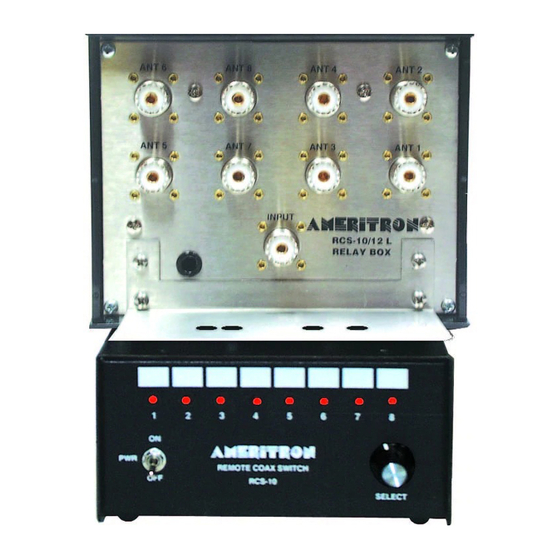
AMERITRON RCS-10 Instrukcja obsługi - Strona 7
Przeglądaj online lub pobierz pdf Instrukcja obsługi dla Przełącznik AMERITRON RCS-10. AMERITRON RCS-10 16 stron. Remotec coax switch

Ameritron RCS-10
Logic Table
Ant 1
Ant 2
A (1)
Off
On
B (2)
Off
Off
C (4)
Off
Off
Note that Ant 1= BCD 0 (0+0+0=0) counting up to Ant 8 which is BCD 7 (1+2+4=7).
LIGHTNING PROTECTION NOTE!
Antenna port "ANT 1" is selected anytime control box voltage is removed, regardless of
selector switch position. If you do not need all eight ports, antenna port "ANT 1" can be
shorted directly to ground to improve lightning protection. You can ground port "ANT 1"
by installing a PL-259 with the center pin shorted to the connector shell. If you use all
ports, try to put the smallest and lowest antenna on port 1. This will minimize risk of
lightning damage.
See Lighting Protection on page 8 for more details.
The control cable can use relatively small size wires. Large rotor cables are unnecessary,
maximum control current is less than 160mA per conductor and voltage is less than 15
volts. The ground connection carries a maximum current of 280mA, but ground current
also flows over the coax shields and other paths without harmful effects. Standard
outdoor-rated 24-gauge or heavier telephone wire is adequate even with cable runs of 500
feet or longer. The main considerations are cable life when exposed to the weather, rather
than current carrying. Control cable conductor resistance must be under 20 ohms for
reliable switching.
INSTALLATION GUIDELINES
The relay unit can be installed either indoors or outdoors. Wherever the unit is
installed, heed the following guidelines:
Always mount this unit with the connectors facing down.
Do not attempt to seal the cover. This unit must be allowed to exchange air through
imperfect sealing, or it may collect moisture.
Avoid mounting locations that have an unnecessary concentration of water, such as
corners of buildings under water runoff. Never mount the switch lower than the
maximum expected height of snow or water.
Ground the mounting bracket by clamping it directly to a tower or mast, or running wide
copper flashing from it to a good earth ground.
Ant 3
Ant 4
Ant 5
Off
On
Off
On
On
Off
Off
Off
On
Instruction Manual
Ant 6
Ant 7
Ant 8
On
Off
On
Off
On
On
On
On
On
160mA
80mA
40mA
5
