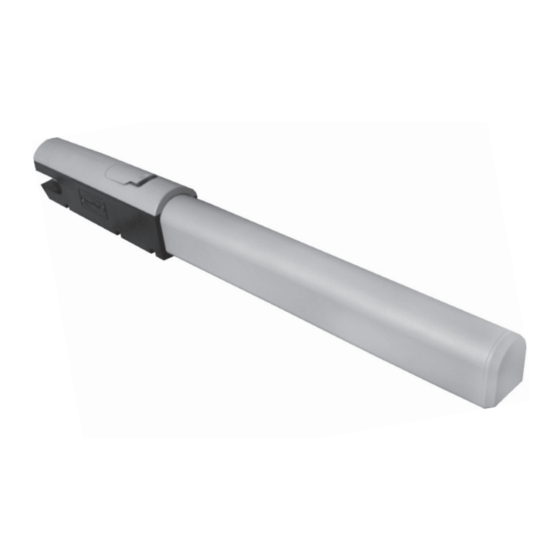
DoorHan SWING-5000 Instrukcja instalacji i obsługi - Strona 9
Przeglądaj online lub pobierz pdf Instrukcja instalacji i obsługi dla Otwieracz do bram DoorHan SWING-5000. DoorHan SWING-5000 16 stron.

5.2. Control BloCk termInals
power supply connector (J1)
~220–240 V (re, n, l) — connector on the control unit used for connection to supply voltage unit.
pe — connection to earth
n — power supply (neutral)
l — power supply (phase)
Connector for electric operators and signal lamp (J7)
1-2-3. m1 (terminals cOm/OO/cl) — for connection of the first electric operator. can be used to open one leaf (in case
of motorized wicket or motorized single-leaf gate).
4-5-6. m2 (terminals cOm/OO/cl) — for connection of the second electric operator. Cannot Be used to open one leaf.
7-8. lamp — output for connection of a signal lamp (230V~40 W max).
Connectors for accessories (J4 for 9-19 terminals, and J3 for 20-21 terminals)
9-10. s-B-s — command "full opening": after closing the contacts of the device connected to these terminals, the control unit
will actuate full opening or closing of both leaves of the gate.
In order to connect several devices, you should connect nO contacts of these devices parallel.
11-12. ped — command "pedestrian passage" or "close": after closing the contacts of the device connected to these terminals,
the control unit will actuate stepped opening or closing of the first leaf of the gate.
In order to connect several devices, you should connect nO contacts of these devices parallel.
13-15. op foto — contacts for connection of opening safety devices (nc): these connections are designed to prevent people,
animals and other objects from being hit by the opening gate. If the device responses when the operator is activated than the gate
leaves reverse or stop immediately and continue to move afterwards. response of the device does not effect operation of the
closing gate.
If the gate is closed and the device has responded, the gate will remain stationary.
WarnInG! If these terminals are not used, install a jumper between contacts 13-15.
14-15. Cl foto — contacts for connection of closing safety device (nc): these connections are designed to prevent people,
animals and other objects from being hit by the closing gate. If the device responses when the operator is activated than the gate
leaves reverse or stop immediately and reverse afterwards (in case this function is preset). Response of the device does not effect
operation of the opening gate.
If the gate is closed and the device has responded, the gate will remain stationary.
WarnInG! If these terminals are not used, install a jumper between contacts 14-15.
16-17. stop — if there is a wicket in the gate these contacts are used for connection of safety devices with nc contacts. After
breaking the contacts of the device connected to these terminals, the control unit will stop any gate movement. In order to connect
several devices, you should connect nc contacts of these devices in series.
WarnInG! If these terminals are not used, install a jumper between contacts STOp.
18-19. +24 V — plus for accessory power supply.
WarnInG! maximal permissible current in these terminals must not exceed 500 mA. calculate carefully the total current,
consumed by the devices.
20-21. sloCk — electromechanical lock supply voltage output. If required, connect 12 V electromechanical lock between the
terminals 20 and 21.
electrIcal connectIons
9
