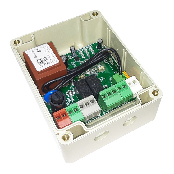
DoorHan CV01 Podręcznik - Strona 5
Przeglądaj online lub pobierz pdf Podręcznik dla Jednostka sterująca DoorHan CV01. DoorHan CV01 8 stron.
Również dla DoorHan CV01: Instrukcja instalacji i obsługi (4 strony), Instrukcja obsługi (12 strony)

2. Operation Mode
By successive pushing the remote control unit button or
switch button, the control unit will execute a series of step con
trol commands (opening – stop – closing – stop).
Execution of the commands is shown by indicators Up and
Dwn. Programming shall be made in standby mode when only
the PWR indicator is on. The PWR indicator is on when the
control unit is energized. Button "P" is used for adjustment of
remote control units for DoorHan receiver.
DESCRIPTION OF OPERATION MODES
Mode one is used to control an electric lock by impulse con
trol signal (2 sec.).
Modes two and three with long signal (70–90 sec.) are used
to control tubular motors of all types.
Mode four is used to control indoor lighting from the switch
and (or) the remote control unit.
OPERATION MODE ADJUSTMENT
Press button "T" for 2 sec. and release one, two, three or
four times to select the desired control mode having guided by
the indicator Up flashing:
Up indicator flashes one time — the motor will stop in 2 sec.
Up indicator flashes two times — the motor will stop in 70 sec.
Up indicator flashes three times — the motor will stop in 90 sec.
Up indicator flashes four times — the motor will not stop (to
control lighting or other devices remotely or stationary).
Default setting is mode four.
DOORHAN REMOTE CONTROL UNIT ENCODING
In standby mode press the button "P" and hold it down until
the Dwn indicator starts flashing (1–2 sec.), after that press the
necessary button on the remote control unit for 1–2 sec.
CODE DELETION
In standby mode press the button "P" and hold it down until
the Dwn indicator is on and then off (10–12 sec.).
Thank you for purchasing DoorHan product. We believe you will be satisfied with its quality. For information on purchasing, distribu
1 bld., 120 Novaya street, Akulovo village, Odintsovo city, Moscow region, 143002, Russia
Phone: +7 495 933-24-33 | www.doorhan.com | e-mail: [email protected]
5
tion and servicing contact DoorHan regional offices or central office:
5. WIRING
Contact function (Fig. 1, 2, 3):
1. Supply mains neutral ~220 V.
2. Supply mains phase ~220 V.
3, 4. Connector for jumper (if required).
5. Direction "open" of operator (black wire).
6. Common (blue) wire of the operator (neutral).
7. Direction "close" of operator (brown wire).
8. Direction "close" of switch.
9. Common wire of switch.
10. Direction "open" of switch.
11, 12. +/ Power of external radio receiver (12 V).
13, 14. Connection NO control contacts of external radio
receiver or keyswitch.
6. SAFETY INSTRUCTIONS
1. Only trained personnel can carry out installation and main
tenance of the control unit in accordance with the safety in
structions.
2. Do not mount the control unit close to heaters. Distance be
tween the control unit and a heater must be more than 1 m.
3. In case of faulty operation of the control unit, disconnect the
control unit from the mains and contact the support service
specialist.
