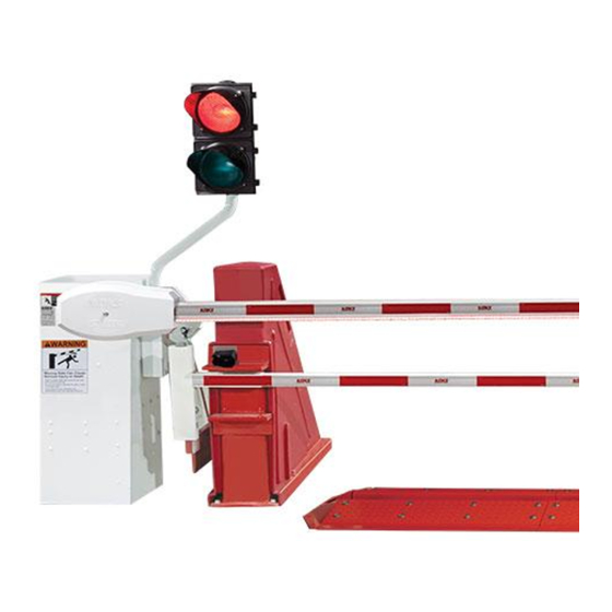
DoorKing 1620 Series Instrukcja instalacji - Strona 9
Przeglądaj online lub pobierz pdf Instrukcja instalacji dla Bariery automatyczne DoorKing 1620 Series. DoorKing 1620 Series 20 stron. Lane barrier
Również dla DoorKing 1620 Series: Instrukcja instalacji (16 strony)

12 ft Layout
Left Hand Mount
2'
2' 3"
2' 3"
10.5"
7"
3' 9"
6"
1.25"
concrete
Right Hand Mount
2'
6'
7"
6"
concrete
14 ft Layout
Left Hand Mount
2'
2' 3"
2' 3"
10.5"
7"
3' 9"
6"
1.25"
concrete
Right Hand Mount
2'
6'
7"
6"
concrete
1620-065-K-11-21
12'
13' 10" with Covers Installed
13'
3'
2'
2'
17' 3"
12'
13' 10" with Covers Installed
2' 6"
13'
3'
2'
2'
17' 3"
14'
13' 10" with Covers Installed
13'
3'
3'
19' 3"
14'
13' 10" with Covers Installed
2' 6"
13'
3'
3'
U-Channel Assemblies required for 12 Ft Lane
2 ea. 3-ft Channel
2 ea. 2-ft Channel
2 ea. End Cap
2'
2' 6"
7"
3'
6"
Traffic Direction
2'
10.5"
7"
3'
1.25"
Traffic Direction
U-Channel Assemblies required for 14 Ft Lane
4 ea. 3-ft Channel
2 ea. End Cap
2' 6"
7"
3'
3'
Traffic Direction
7"
3'
3'
19' 3"
Traffic Direction
7
GENERAL NOTES
• Automated vehicular gates
shall be designed and installed
to be in strict compliance with
the UL 325 Safety Standard
and the ASTM F2200
Construction Standard.
• Automated vehicular gates
that do not meet the
requirements of these
standards shall not be allowed.
• This drawing is for the sole
purpose of general gate
6'
operator foot-print and
location, photo beam coverage
and placement, and vehicular
loop dimensions and
placement. Drawings are
not all inclusive or guaranteed
to scale.
• No considerations have been
made for grade, existing public
utilities, landscape, drainage,
site peculiarities, or
requirements by the authority
having jurisdiction, ie; Fire
Marshall, Building Inspector,
2' 3"
Street and Alley Departments.
2' 3"
• Warning Signs must be
installed and must be highly
visible upon both entry and
exit of the property, and must
remain in place for the life of
3' 9"
the gate operating system.
6"
• Proper lane identification and
vehicular
direction signs should be
highly visible upon entry onto
the property.
• Gate dimensions, posts,
guide rollers, photo beams,
reversing edges, hinges, and
other gate hardware may vary
in size, dimension, and
placement and should not be
used as an exact reference.
• All loop sizing and placement
dimensions indicated are
2'
solely intended for reference
only, and not intended to be
the final criterion for
determining the loop sizing
and placement on any
automated vehicular gate
project.
6'
DoorKing, Inc does not
assume responsibility or
liability for any installation
6"
with regard to equipment/sys-
tem malfunction, vehicle
detector loop sizing and
placement, or consequent
damages or injuries caused
thereby.
• DoorKing, Inc. does not
2'
assume responsibility or
liability for the installation and
unauthorized changes to the
2' 3"
design and operation of
2' 3"
equipment, or alterations to
the final site plan.
10.5"
•
3000 psi reinforced
concrete - minimum depth
3' 9"
six (6) inches.
6"
1.25"
•
Allow a minimum of six
(6) inches around all
components.
•
Concrete pad size shown
is minimum requirement.
