Flycam HD-5000 Instrukcja montażu - Strona 6
Przeglądaj online lub pobierz pdf Instrukcja montażu dla Akcesoria do kamer Flycam HD-5000. Flycam HD-5000 10 stron. Video stabilizer
Również dla Flycam HD-5000: Instrukcja obsługi (11 strony), Instrukcja obsługi (16 strony)
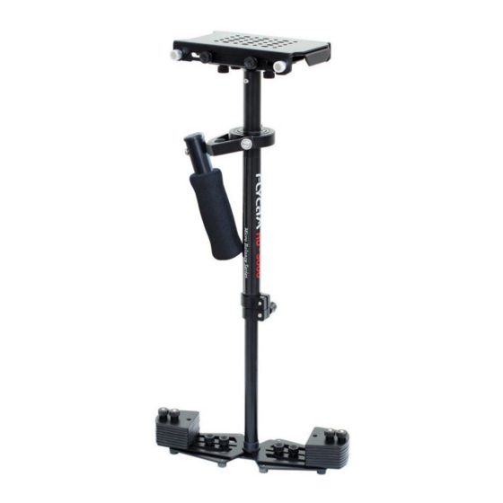
Vertical Adjustment of telescopic central
post (Part-2) is made by loosening the con-
trol located at the base, raising or lowering
the post to desired location and then re-
tightening the vertical control. Do not over-
tighten this control.
Balancing your Flycam Stabilizer
Before beginning the balancing process check the following:
Camera is securely attached to Head Plate
Lens cap is removed and secured
Telescoping Clamp is tightened
Weight discs are added successfully
All screws are tightened securely
Battery, all accessories and cables are secured
Balancing the Horizontal Axis
When your Flycam HD Stabilizer is properly assembled, you can start the test and setup of
tal balance. Horizontal Balance allows the camera to remain level, during operation, with the Central
Post in a vertical position unless off-axis framing is desired.
When testing for horizontal balance start from a flat and level surface like table. This will allow the stabi-
lizer to hang freely as you hold it. If your stabilizer is correctly balanced on its horizontal axis, then it will
be both leveled & upright, with Central Post in a perfect vertical position.
NOTE: If you do not have enough weight on Base Platform the entire Flycam could flip upside down. If this
movement starts to happen, be ready to catch the sled before a complete 180° occurs. This type of un-
wanted movement requires more weight to be added to the base with additional weight discs.
Another way to accomplish Horizontal Balance is to move the center of gravity of camera by re-
mounting the camera to a different area of the Head and Mid Plate, either front-to-back or side-to-side.
If the stabilizer be front heavy, loosen the screws on the sides of Head Plate and gently slide Head Plate
back until optimum balance is achieved. Tilting to the back means the load is tail heavy requiring the
plate to be adjusted forward on the head.
If the stabilizer leans towards right, then loosen the screws on the bottom of Bottom Plate and gently
slide the Mid Plate towards left. If it leans to left, then adjust the Mid Plate towards right. A bit at a time
until balance is achieved.
6
25
horizon-