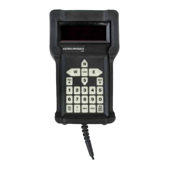
ASTRO-PHYSICS 1568GTO Instrukcja obsługi technicznej - Strona 13
Przeglądaj online lub pobierz pdf Instrukcja obsługi technicznej dla Keypad ASTRO-PHYSICS 1568GTO. ASTRO-PHYSICS 1568GTO 17 stron.

7. Remove lithium battery wires from the red plastic molded clamp.
8. first, take note of the pigtail wire positions relative to the sides of the battery
holder so that you orient the new battery correctly. carefully remove the bat-
tery from the battery holder as shown with your small flat blade screwdriver.
(see photo below right)
to completely remove the lithium battery: caRefullY guide the lithium bat-
tery wires under the fiber-optic cables.
install the battery
1. be sure that you are installing the correct battery! the astro-Physics
part number is e0334. the battery is a cR2430 and will have a 2.5"
pigtail spot-welded to it. this battery must be purchased from astro-
Physics.
2. guide the lithium battery wires under the fiber-optic cable and plug it
into the battery connector. the black lead is normally to the outside.
note: the battery connector is keyed to prevent plugging it in back-
wards. in the proper orientation, it plugs in quite easily.
do not force the plug! You could damage the pins on the recep-
tacle!
3. snap the battery into its carrier.
4. snap the battery wires into position by pushing
them into the spacer's molded clamp. be care-
ful not to catch any fiber-optic cables!
5. gently pull the fiber-optic cable away from the
window before replacing the display. You do
not want to crush or sharply bend any of the
fibers.
use care when replacing the display to not scratch the window or to
damage any of the optical fibers. carefully place the display in the
front of the case
6. Plug the display cable into the display header making sure the pins
are aligned
7. When placing the back on the unit, first be sure that all six spacers
are in place on the screws. then, make sure the screws are aligned
with the proper holes. start by aligning the two screws on one side of
the display. make sure that all wires, fibers and cables will be safely
inside the unit. line up the display end before moving to the cable end of the keypad.
8. the cable strain relief may need to be held and guided gently into the cutout in the case to finish mating the two halves.
9. make a final check to be sure that no wires, fibers or cables are caught between the front and back halves of the key-
pad.
10. carefully apply a small amount of pressure
to hold the back down while tightening all
six screws.
11. Replace the KeYPRo Keypad Protector
following the instructions in the document
referenced previously. You should now be
ready to reinstall your database.
12
