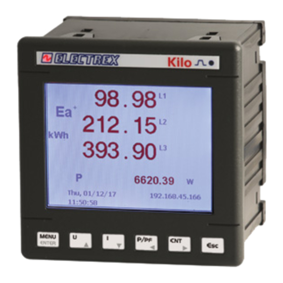
Electrex EXA 96 Instrukcja instalacji - Strona 3
Przeglądaj online lub pobierz pdf Instrukcja instalacji dla Przyrządy pomiarowe Electrex EXA 96. Electrex EXA 96 4 stron.
Również dla Electrex EXA 96: Instrukcja instalacji (4 strony)

NOTE n.1
3P4W
3 phases 4 wires
2P2W
2 phases 2 wires
1P2W
1 phases 2 wires
3I
3 phases 2 wires
3P3W-B-3U
1 phases 3 wires
3P4W-B-3U
1 phases 4 wires
3P3W-B
1 phases 2 wires
3P4W-B
1 phases 2 wires
3P3W
2 phases 3 wires
NOTE n.2
POWERS
Integration time of the average value (AVG) and peak value (MD) for
Power (from 1 to 60 minutes).
CURRENTS
Integration time of the average value (AVG) and peak value (MD) for
Current (from 1 to 60 minutes).
NOTE n.3
NORMAL
Classic Alarm with reference to a fi xed threshold or to maximum and
minimum delay and applicable hysteresis. "AVG" parameter is not used.
UNBAL%
Considers also the 2 following registers of the selected one in "MEAS".
"THRE" parameter becomes a % value. Alarm goes on when one of the
three register is diff erent from the percentage set on "THRE" comply with
the higher value of the three read register if "MAX" is set on "TYPE", or
comply with the lower value of the three register if "MIN" is set on "TYPE"
With delay and applicable hysteresis.
UNBAL
Considers also the 2 following registers of the selected one in "MEAS".
"THRE" parameter becomes a
three register is diff erent from the percentage set on "THRE" comply with
the higher value of the three read register if "MAX" is set on "TYPE", or
comply with the lower value of the three register if "MIN" is set on "TYPE"
With delay and applicable hysteresis.
3-OF-3
Considers also the 2 following registers of the selected one in "MEAS".
It operates on a fi xed max or min threshold with delay and applicable
hysteresis. When all the three registers exceed the threshold the alarm
goes ON. "AVG" parameter is not used.
1-OF-3
Considers also the 2 following registers of the selected one in "MEAS".
It operates on a fi xed max or min threshold with delay and applicable
hysteresis. If one of the three registers exceeds the threshold the alarm
goes ON. "AVG" parameter is not used.
NOTE n.4
MAX
Alarm setting in excess or in decrease compared with the predefi ned
MIN
conditions.
With the exception of "UNBAL and UNBAL%".
NOTE n.5
MEAS
Indicates which register (measure) the alarm is related to.
See table N.1 Input Register.
THRE
Alarm threshold in absolute value, with the exception made for "UNBAL"
in which the value inserted becomes a percentage.
NOTE n.6
NORMAL
Alarm remains active during the duration of the event. It restores auto-
matically.
HOLD
Alarm remains active until the manual reset via Modbus.
NOTE n.7
ALARM 1
MODBUS alarm (Associated with output 1 if present)
ALARM 2
MODBUS alarm (Associated with output 2 if present)
ALARM 3
MODBUS alarm (Associated with output 3 if present)
ALARM 4
MODBUS alarm (Associated with output 4 if present)
NOTE n.8
OFF
LED-1
S0-1, 2, 3, 4
NOTE n.9
EA
Power (Energy) Active Imported / Exported
ER L
Power (Energy) Reactive Inductive Imported / Exported
ER C
Power (Energy) Reactive Capacitive Imported / Exported
ES
Power (Energy) Apparent Imported / Exported
EA+
Power (Energy) Active Imported
ER L+
Power (Energy) Imported Inductive Reactive
ER C+
Power (Energy) Imported Reactive Capacitive
ES+
Power (Energy) Apparent Imported
EA-
Power (Energy) Active Exported
ER L-
Power (Energy) Exported Inductive Reactive
ER C-
Power (Energy) Capacitive Reactive
ES-
Power (Energy) Apparent Exported
NOTE n.10
YES
Referred to the primary of the current transformer (CT)
NO
Referred to the secondary of the current transformer (CT)
ALARM SETUP EXAMPLE
Alarm (latching) when the average active power (MEAS 344) exceeds the value of 100
kW, hysteresis of 5% and delay of 5 seconds; set the parameters as in the table:
ALARM 1 (note n.7)
NORMAL, UNBAL%, UNBAL,
MODE (note n.3)
3-OF-3, 1-OF-3
DIRECTION (note
MAX, MIN
n.4)
DATA ADDRESS
Controlled measure. See table n.1 for register
(note n.5)
selection
THRESHOLD (note
Threshold value
n.5)
HYSTERESIS
1...99 (%)
ON DELAY
1 sec ...99 minutes
OFF DELAY
1 sec ...99 minutes
OUT MODE (note
NORMAL, HOLD
n.6)
Star
Two-phases
Single phase
3 Current Inputs single phase o three phases
Balanced triangle
Balanced star
Balanced triangle
Balanced star
Triangle
value. Alarm goes on when one of the
The instrument's LED remains off
The instrument's LED fl ashes according to the
selected pulse generator
SETUP SEQUENCE
PAGE
ANALOG OUT 1
ANALOG OUT 1
MEAS
200
MODE
4-20
MIN
0.000
MAX
0.000
ANALOG OUT 2 (see ANALOG OUT 1)
Analog output
10
11
12
For loads with impedance less than or
equal to 250 ohms.
AO1
10 11
12
13
19
20
AUX IN/OUT
Max 250 ohm
NORMAL
MAX
344
NOTE: A
+100.0 K
MEAS
Indicates which register (and thus measure) the alarm is related to.
05
See Table N.1 (Input registers).
05 SEC
NOTE: B
01 SEC
MIN
Associated scale value starts at 0 and 4 mA
NORMAL
MAX
Full scale value associated with 20 mA
ANALOG OUTPUT
PARAMETERS
VALUES AVAILABLE
DATA ADDRESS
Controlled measure. See table n.1
(note A)
for register selection
MODE
0-20, 4-20
MIN (note B)
MAX (note B)
19
C
Common (negative)
20
1
Output 1 (positive)
21
2
Output 2 (positive)
For loads with higher impedance of 250
ohms it is necessary to include in series an
external power supply. The voltage to be
applied is given by the following formula:
V = (R-250) x 0.027
(E.g. with an impedance of 1 Kohm, the
voltage to be applied is:
(1000-250) x 0.027= 20.25 Vdc
AO2
21
22
AO1
10 11
12
13
19
AUX IN/OUT
R max = (Vdc / 0.027) + 250
Vdc
5
9
12
24
DEFAULT
000
4-20
0.000
0.000
N L
230 V~
24V =
- +
AO2
20
21
22
R max
435
583
694
1138
