Electrex KILO Instrukcje - Strona 3
Przeglądaj online lub pobierz pdf Instrukcje dla Przyrządy pomiarowe Electrex KILO. Electrex KILO 4 stron.

5
RS485 CONNECTION
The instrument has three terminals for connection to the RS485 port. The connection must be
carried out using a twisted pair inserted in the appropriate screw terminals (see Fig. 16). The
terminals marked "A" and "B" indicate the polarity of the contacts. There is also a terminal identified
by the symbol
for connecting the shield (sheath) of the twisted pair to be used for network
installation in high interference environments or in the presence of strong currents. The polarity of
the contacts must be observed when the connection is made (see also the indications on the label).
Shield
(sheath)
It is recommended to use a twisted pair cable with minimum section of 0,36 mm
characteristic impedence 120W and with capacity lower than 60 pF/m.
6
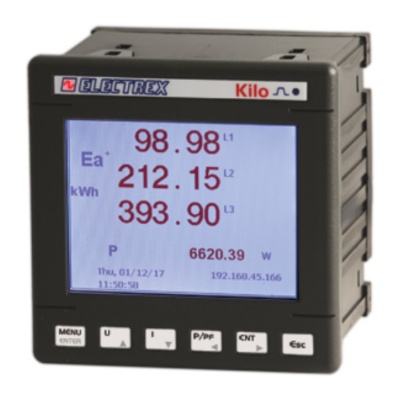
KEYBOARD DESCRIPTION
Instrument programming can be carried out on the keyboard located on the instrument's front
panel. The keys for displaying the measurements, consumptions, temperature and the clock calendar
each have a green LED which lights up when that function is utilised. The L1, L2 and L3 keys each
have a red LED which lights up when that function (display of the phase measurements) is utilised.
KILO
3 PHASE ENERGY ANALYZER/CONTROLLER
?
Key for access to programming and reset
?
High luminosity display (adjustable)
?
Key for phase selection (cursor keys during programming)
?
Key for displaying the calendar/clock and the temperature
?
Key for displaying the consumption of Three-phase Reactive Energy (kVArh) and of the
auxiliary contacts
?
Key for displaying the consumption of Three-phase Active Energy (kWh)
?
Key for displaying Three-phase instantaneous, average and peak Apparent Power
(VA)measurements and the three-phase instantaneous Reactive Power (VAr)
?
Key for displaying three-phase instantaneous, average and peak Active Power (W)
measurement and Power Factor (Cos f)
?
Key for Voltage and Current display
6.1
MEASUREMENT RELATED FUNCTION PROGRAMMING
The writing "ELECTREX" appears when the instrument is powered. After a few seconds the
voltage and current measurements will be displayed (the LED on the key is lighted). To enter
into programming mode, press simultaneously the programming access key (see Fig.18) and
the key.
KILO
3 PHASE ENERGY
The default settings provide:
- Low voltage measurement
- 4-wire connection (STAR)
- CT ratio = 1
- Integration time = 15 minutes
6.1.1 measurement functions SELECTION
The instrument can carry out measurements on both low and high voltage. The display will
show the first selection (direct measurements in low voltage):
ELECTREX S.r.l. via Claudia, 96 - 41096 Savignano s/P (MO) - Italy - Tel. +39.59.796372 Fax. +39.59.796378
Fig. 16
A B
+ -
(22 AWG)
2
The key for access to
prgramming is located under
the writing "ELECTREX"
between the letters E and L
SUBJECT TO CHANGE WITHOUT NOTICE
KILO
KILO M
By pressing the key
the second selection will be displayed (measurements in high
voltage with VTs):
Press the key
on the page selected and proceed to program the other functions.
6.1.2 VT
TRANSFERTION RATIO MEASUREMENTS HIGH VOLTAGE
SELECTION
Select "VOLT HIGH" to access the programming page which enables the setting of the
transformation ratio of the VT utilised. The display will show:
Flashing digit
The key
increases the digit to be set (flashing).
The key
decreases the digit to be set (flashing).
The key
enables moving from one digit to another (from the more significant digit to
the less significant digit). Once the last digit is set, this key enables programming of the
transformation ratio of the VT and access to the next programming page.
6.1.3 CONNECTION TYPE SELECTION (STAR OR DELTA)
Selecting"VOLT LOW" on the first programming page or after setting the VT ratio, (having
selected "VOLT HIGH" on the first measurement page) select the type of connection. The
instrument can be connected to 4-wire networks (CONN 4W) or three wire networks (CONN
D 3W). The display will show:
By pressing the key
the second selection will be displayed:
Press the key
on the page which contains the connection wanted and proceed to the
programming of the other functions.
6.1.4 CT TRANSFERTION RATIO SELECTION
After selecting the type of connection (star or delta) the CT transformation programming page
appears. The display will show:
Flashing digit
The key
increases the digit to be set (flashing).
The key
decreases the digit to be set (flashing).
The key
enables moving from one digit to another (from the more significant digit to
the less significant digit). Onced the last digit is set, this key enables programming of the CT
transformation ratio and access to the next programming page.
6.1.5 AVERAGE POWERS INTEGRATION TIME SELECTION
The last programming page enables the setting of the integration time (in minutes) on which
the averages of Active Power and Apparent Power will be calculated. The display will show:
Flashing digit
The key
increases the digit to be set (flashing).
The key
decreases the digit to be set (flashing).
The key
enables moving from one digit to another (from the more significant digit
02/2004
Instructions
English
