Baumer Hubner Berlin PMG10 Instrukcja obsługi - Strona 3
Przeglądaj online lub pobierz pdf Instrukcja obsługi dla Konwerter mediów Baumer Hubner Berlin PMG10. Baumer Hubner Berlin PMG10 44 stron. Absolute encoder
Również dla Baumer Hubner Berlin PMG10: Instrukcja montażu i obsługi (32 strony), Instrukcja montażu i obsługi (32 strony)
Baumer Hübner
6.6
LED activity indicator .......................................................................................................................... 23
6.7
Output switching behavior Speed switch (optional) ............................................................................ 23
6.8
Electrical connection with radial terminal boxes ................................................................................. 24
6.8.1
Connecting the supply cable ................................................................................................. 24
6.8.2
Pin assignment first terminal box .......................................................................................... 26
6.8.3
Assignment of connection elements second terminal box .................................................... 27
6.9
Electrical connection with radial flange connector .............................................................................. 27
6.9.1
Connecting the supply cable ................................................................................................. 27
6.9.2
Assignment first flange connector ......................................................................................... 29
6.9.3
Assignment second flange connector ................................................................................... 30
6.10 Z-PA.SDL.1 WLAN adapter: Programming device for HMG10P/PMG10P ........................................ 31
6.11 Sensor cable and round connector..................................................................................................... 31
6.11.1
Sensor cable ......................................................................................................................... 31
6.11.2
Round connector M23........................................................................................................... 32
6.11.3
Round connector M23, 17-pin with sensor cable HEK17 ..................................................... 32
6.11.3.1
6.11.3.2
7 Disassembly................................................................................................................................................. 35
7.1
Uninstall when using EURO flange B10 ............................................................................................. 36
7.1.1
Uninstall encoder from drive shaft ........................................................................................ 36
7.2
Uninstall with base B3 ........................................................................................................................ 38
7.2.1
Uninstall encoder from drive shaft ........................................................................................ 38
8 Technical data.............................................................................................................................................. 40
8.1
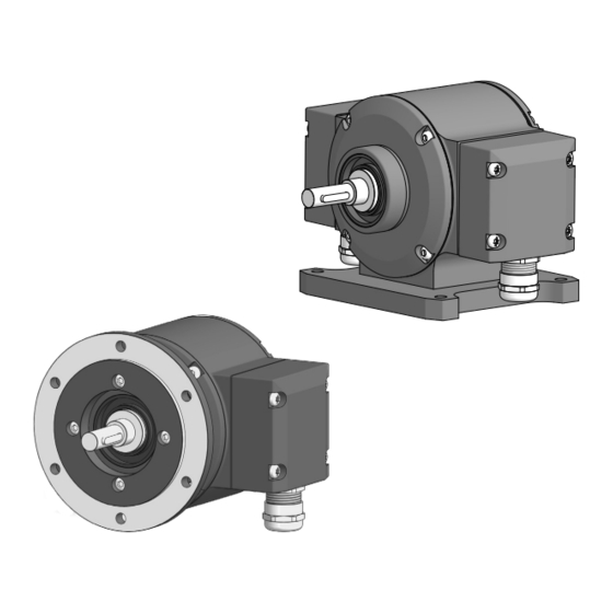
Solid shaft encoder dimensions with EURO flange B10..................................................................... 41
8.1.1
With radial terminal boxes..................................................................................................... 41
8.1.2
With radial flange connectors................................................................................................ 42
8.2
Solid shaft encoder dimensions with housing base B3....................................................................... 42
V1 | PMG10 & PMG10P SSI
For devices w/o additional incremental output ................................................. 32
For encoders with additional incremental output .............................................. 34
Operating Manual
List of contents
iii