Baumer Camera Link HXC20c Skrócona instrukcja obsługi - Strona 2
Przeglądaj online lub pobierz pdf Skrócona instrukcja obsługi dla Aparat cyfrowy Baumer Camera Link HXC20c. Baumer Camera Link HXC20c 2 stron.
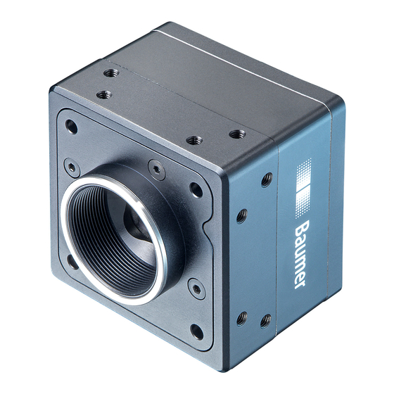
General Description
1
2
3
6
5
No.
Description
No.
Description
1
(respective) lens mount
4
Digital-IO supply
2
Power supply
5
CameraLink
3
CameraLink
®
Full socket
6
Signaling-LED
Camera Link
®
Interfaces
Notice
CL FULL
CL FULL
The camera has two CameraLink sockets. To differentiate bet-
Baumer
Type: HXCXXx (xxxxxxx)
ween CameraLink Base and CamerLink Full socket, please look
S/N:
000XXXXX
R1.0
at the label. You can not use the CL Full socket alone!
CL BASE
CL BASE
Caution
When fixing the CameraLink
®
cable with too much force the
screws might get damaged.
The maximum torque is 2.5 inch lbf [0.3 Nm].
Base Camera Link
®
Pin
Signal
Pin
Signal
Pin
1
GND
14
GND
1
GND
2
X0-
15
X0+
2
Y0-
3
X1-
16
X1+
3
Y1-
4
X2-
17
X2+
4
Y2-
5
XCLK-
18
XCLK+
5
YCLK-
6
X3-
19
X3+
6
Y3-
7
SERTC+
20
SERTC-
7
100 Ω term.
8
SERTFG-
21
SERTFG+
8
Z0-
9
22
9
CC1-
CC1+
Z1-
10
CC2+
23
CC2-
10
Z2-
11
CC3-
24
CC3+
11
ZCLK-
12
CC4+
25
CC4-
12
Z3-
13
GND
26
GND
13
GND
LED Signaling
4
LED
1
Base socket
®
2
Power Supply / IO Pin Assignment
Caution
A power supply with electrical isolation is required for proper operati-
on of the camera. Otherwise the device may be damaged.
M8 / 3 pins
Full Camera Link
®
1
(brown)
3
(blue)
4
(black)
Signal
Pin
Signal
14
GND
15
Y0+
16
Y1+
17
Y2+
18
YCLK+
19
Y3+
20
100 Ω term.
21
Z0+
22
Z1+
23
Z2+
Power VCC
24
ZCLK+
25
Z3+
26
GND
1
2
Signal
Meaning
green
Power on
yellow
Readout active
green
Transmitting
Configuration comman
red (yellow in both)
processing
M8 / 8 pins
wire colors of the connecting cable
5
6
4
7
3
1
2
8
Power V
1
(white)
Line 9
CC
GND
2
(brown)
Line 1
NC
3
(green)
Line 0
4
(yellow)
GND
5
(grey)
U
ext
6
(pink)
Line 7
7
(blue)
Line 8
8
(red)
Line 2
Power Supply
9,6 VDC .. 30 VDC
I
200 mA .. 625 mA
Heat Transmission
Caution
Provide adequate dissipation of heat, to ensure that the temperature
does not exceed the spedified temperature.
The surface of the camera may be hot during operation and imme-
diately after use. Be careful when handling the camera and avoid
contact over a longer period.
It is very important to provide adequate dis-
T
sipation of heat, to ensure that the housing
temperature does not reach or exceed +65 °C
(+149°F). As there are numerous possibilities for
installation, a specific method for proper heat dis-
sipation is not defined, but the following principles
are suggested:
T: Housing temperature
measurement point
▪
Operate the cameras only in mounted
condition with a good heat conductor
(e.g. aluminum)
▪
Mounting in combination with forced
convection may provide proper heat
dissipation
T