Advanced Axis AX-LED32Y Instrukcja instalacji - Strona 6
Przeglądaj online lub pobierz pdf Instrukcja instalacji dla Jednostka sterująca Advanced Axis AX-LED32Y. Advanced Axis AX-LED32Y 20 stron. Switch led modules

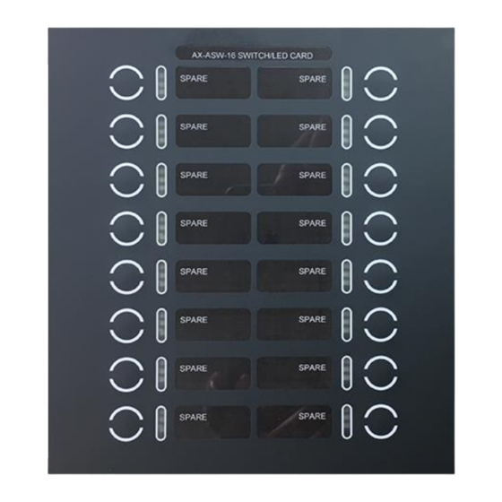
To install a Switch LED Module in a local zone annunciator cabinet, remove the inner plate of the AX-LZA-CAB by
removing the four (4) screws holding the inner plate to the cabinet and removing the inner plate ground wire from
the cabinet pluggable ground stud. Place the Switch LED Module between the four (4) module mounting studs and
secure with the provided washers and nuts (see figure 4). Replace the inner plate and ground wire to the AX-LZA-
CAB.
AX-LZA-CAB1
AX-LZA-CAB2
Inner Door
Inner Door
AX-LZA-CAB4
Inner Door
Figure 4 – Switch LED Module Remote Cabinet Mounting
Note: For detailed AX-LZA-CAB mounting instructions refer to installations instructions provided with the
AX-LZA-CAB.
2.3 AX-I/O-48 Other Cabinet Mounting
In addition to being mounted in cabinets previously mentioned, the AX-I/O-48, Switch LED Driver Module, can also
rd
be installed in an Advanced AX-GCAB (Listed general cabinet) or an ANSI/UL Listed 3
party annunciator
enclosure.
2.3.1 AX-GCAB Mounting
Mount the Advanced AX-GCAB, general purpose UL Listed enclosure, in a clean, dry environment. Remove the
AX-I/O-48 module from its shipping package and securely install it within the AX-GCAB enclosure with the stand-
offs and screws provided with the AX-I/O-48 module (see figure 5).
Figure 5 – AX-I/O-48 General Purpose Cabinet Mounting
6
www.advancedco.com
